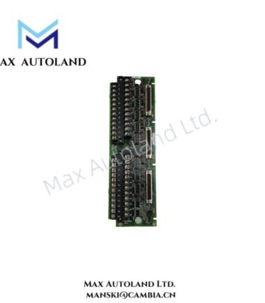
Overview
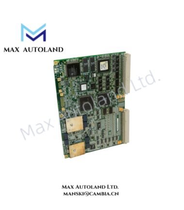
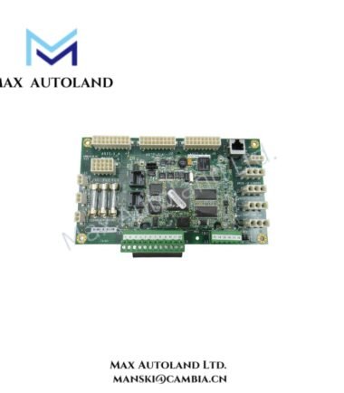
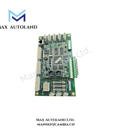
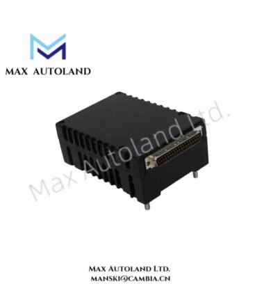
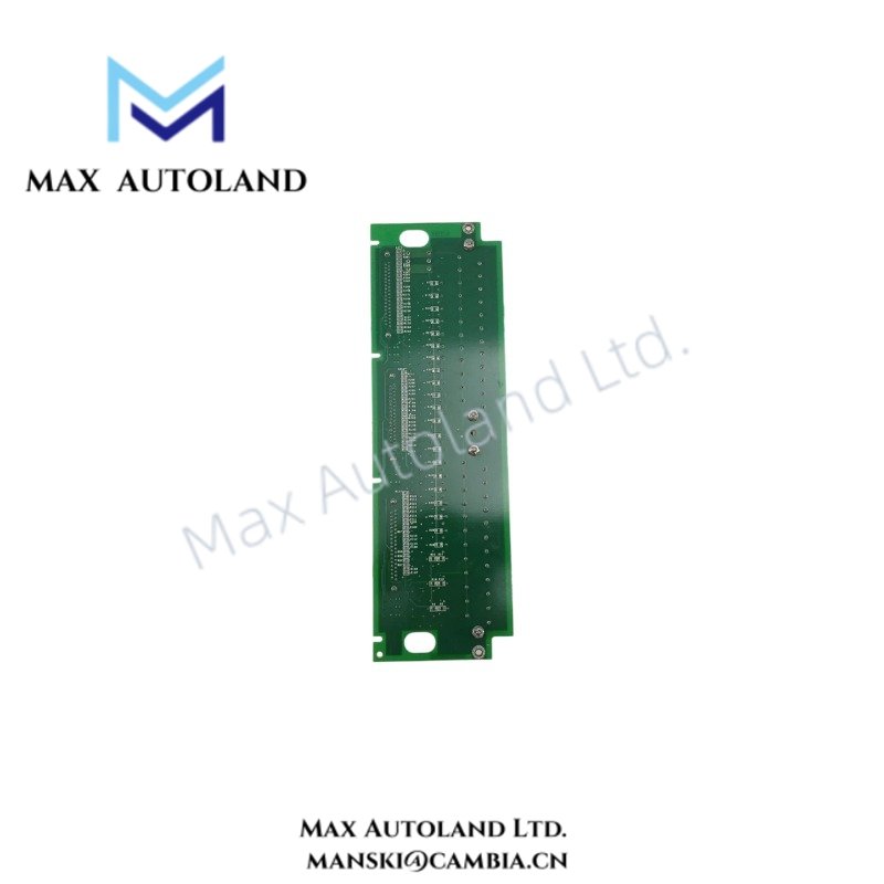
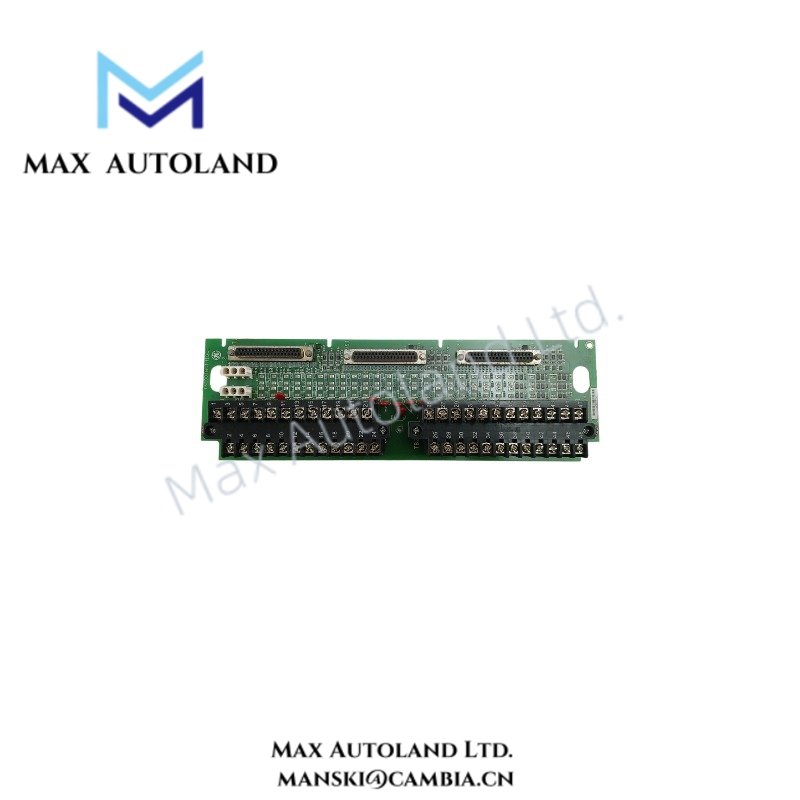
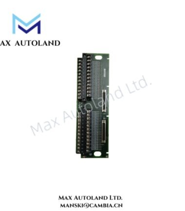
Configured for board-level interface functions in GE Mark VI and EX2100 control architectures, the GE IS200AEBEG1A (IS200AEBEG1A Printed Circuit Board) provides physical and electrical integration within the control assembly. The supplied data identifies it as a GE PCB component used for turbine control and generator excitation applications.
Hardware Specifications
| Parameter | Specification |
|---|---|
| Model | IS200AEBEG1A |
| Brand | General Electric (GE) |
| Series | Mark VI / EX2100 Excitation Control System |
| Product Type | Printed Circuit Board Component |
| Board Function | Bridge Interface / Terminal Board Module |
| Application | Turbine Control and Generator Excitation |
| Mounting | Rack or panel installation within GE control cabinets |
| System Integration | GE Mark control architecture |
| Hardware Indicators | Board-level status indicators where fitted |
GE Industrial Control and Interface Characteristics
The IS200AEBEG1A belongs to the GE industrial control hardware family and supports physical integration between control-system hardware and associated excitation circuitry. Therefore, installation should follow the applicable GE system drawings rather than assuming a generic I/O pin assignment.
The board should also remain within the specified Mark VI or EX2100 hardware configuration. In particular, technicians should verify connector locations, board revision, cabinet slot assignment, and mating hardware before energization.
For firmware or configuration compatibility, use the system-specific GE documentation and approved configuration tools. The supplied data does not define a firmware version, backplane communication rate, or electrical channel count, so these parameters should not be inferred from the model number alone.
Frequently Asked Questions (FAQ)
Q: Is the IS200AEBEG1A a standalone controller?
A: No. The supplied information identifies the IS200AEBEG1A as a PCB component within a GE control architecture. It should therefore be evaluated as part of the complete Mark VI or EX2100 assembly.
Q: Does the supplied data define the board power consumption?
A: No. The supplied specifications do not provide a verified power-consumption value. Use the applicable GE hardware documentation before sizing cabinet power resources.
Q: Can the board be replaced without checking the system configuration?
A: No. Before replacement, verify the complete part number, board revision, connector arrangement, cabinet position, and system documentation. Do not assume interchangeability between visually similar GE boards.
Field Installation Guidelines
- Isolate cabinet power according to the approved plant electrical procedure before removing or installing the PCB.
- Verify the complete IS200AEBEG1A identification and board revision against the system drawing.
- Inspect connectors, mating plugs, mounting hardware, and PCB surfaces for contamination or mechanical damage.
- Install the board only in its designated cabinet or rack position.
- Keep signal wiring separated from high-current and high-voltage conductors where the cabinet design permits.
- Maintain shield termination and grounding practices specified by the GE system drawings.
- Do not alter jumpers, switches, connectors, or wiring unless the applicable hardware documentation explicitly permits the change.
- After installation, inspect connector engagement and mechanical retention before applying power.
- Verify controller diagnostics and board status indications after energization.
- Perform the required functional and loop checks before returning the control system to service.