
Overview
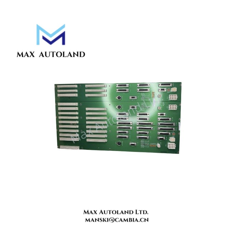
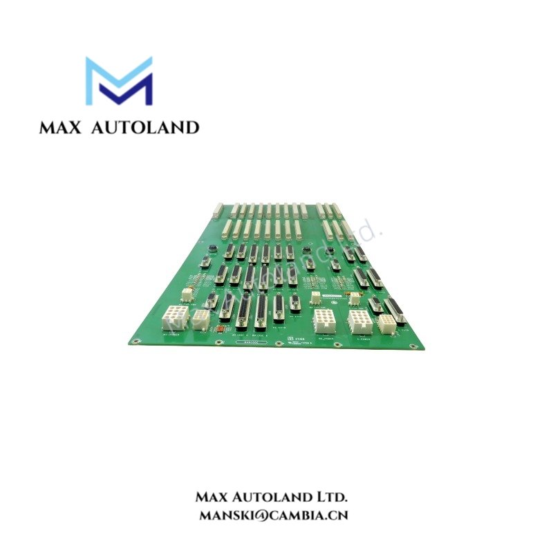
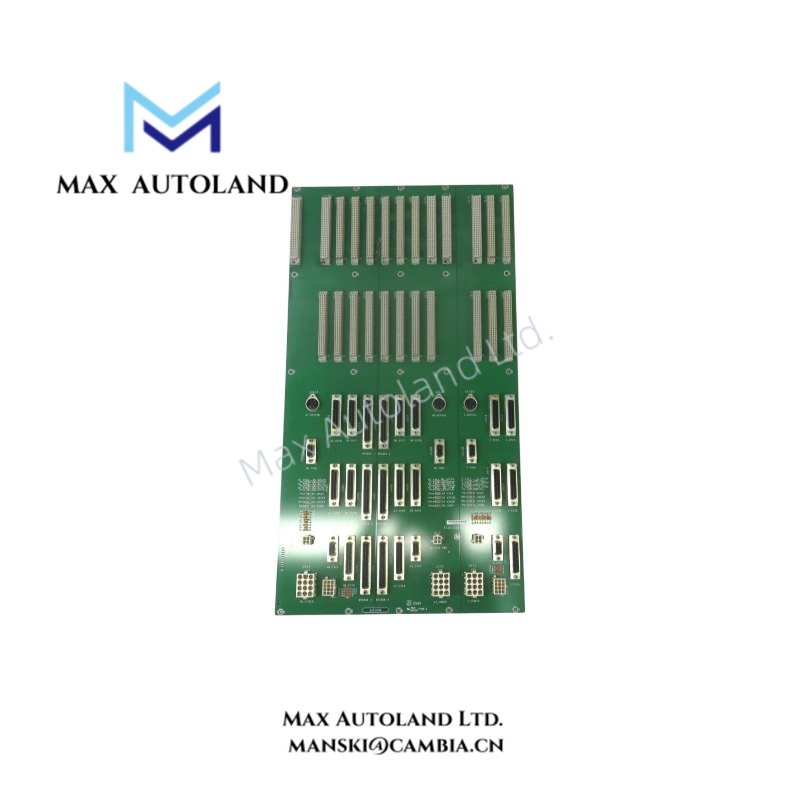
The GE IS200EBKPG1C, also cataloged as the IS200EBKP rack backplane board, provides physical interconnections for controller boards and I/O terminal board cables in the GE EX2100 excitation control system. It contains separate sections for controllers M1, M2, and C, with independent power supply sections and dedicated board connectors. Integrated test points provide access to selected analog-to-digital and digital-to-analog converter signals for hardware diagnostics.
Hardware Specifications
| Parameter | Specification |
|---|---|
| Model | IS200EBKPG1C |
| Base Model | IS200EBKP |
| Brand | General Electric (GE) |
| Series | EX2100 |
| Product Type | Rack Backplane Board |
| Function | Controller board interconnection and I/O terminal board cable interface |
| Controller Sections | M1, M2, and C |
| Power Supply Sections | Independent sections for M1, M2, and C |
| Upper Connectors | 24 DIN connectors |
| Lower Connectors | 27 D-sub connectors, 3 circular DIN connectors |
| Power Supply Plugs | 3 x 12-pin plugs |
| Fan Connections | 3 fan power plugs |
| Diagnostic Points | 30 test points |
Backplane Bus and Controller Interconnections
The IS200EBKPG1C provides the physical connector infrastructure for the EX2100 controller rack. Its three sections accommodate the M1, M2, and C controller configurations.
- M1 section: Accommodates ACLA, DSPX, EISB, EMIO, and ESEL boards.
- M2 section: Accommodates ACLA, DSPX, EISB, EMIO, and ESEL boards.
- C section: Accommodates DSPX, EISB, and EMIO boards.
The backplane connects installed control boards through its DIN and D-sub connectors and provides interfaces for I/O terminal board cables. The board also includes power supply and cooling fan connections. Its test points permit access to selected converter signals for diagnostic measurements.
The available information does not specify bus transmission rates, electrical loading limits, connector pin assignments, or firmware compatibility requirements. These parameters should be verified against the applicable GE EX2100 hardware documentation.
Frequently Asked Questions (FAQ)
Q: Does the IS200EBKPG1C contain controller processing circuitry?
A: The IS200EBKPG1C functions as a rack backplane. It provides physical interconnections for controller boards rather than serving as a standalone controller processor.
Q: What diagnostic facilities are available on this backplane?
A: The board has 30 test points that provide access to signals associated with analog-to-digital and digital-to-analog converters. Refer to the applicable hardware documentation for signal identification and measurement procedures.
Q: Can the IS200EBKPG1C be replaced while the EX2100 system is energized?
A: Hot replacement is not confirmed by the available specifications. Before removing or installing the board, follow the system-specific shutdown, isolation, and discharge procedures specified by GE.
Field Installation Guidelines
- Verify the hardware: Confirm the complete part number, IS200EBKPG1C, and revision markings against the equipment bill of materials and applicable EX2100 documentation.
- Isolate power: Follow the approved system shutdown and electrical isolation procedures before removing the backplane or disturbing connected boards.
- Inspect connectors: Check DIN, D-sub, circular DIN, power supply, and fan connectors for damaged contacts, contamination, or mechanical deformation.
- Check rack alignment: Position the backplane according to the designated rack mounting arrangement. Avoid excessive force when engaging board connectors.
- Route cables correctly: Keep signal wiring separate from power wiring where required by the system design. Maintain connector clearance and avoid cable strain.
- Perform diagnostic checks: Use the documented test-point assignments and approved measurement procedures. Do not apply test equipment to unidentified points.
- Verify the configuration: Confirm controller board positions, power connections, and cooling fan connections before restoring power.