Overview
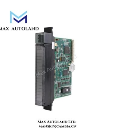
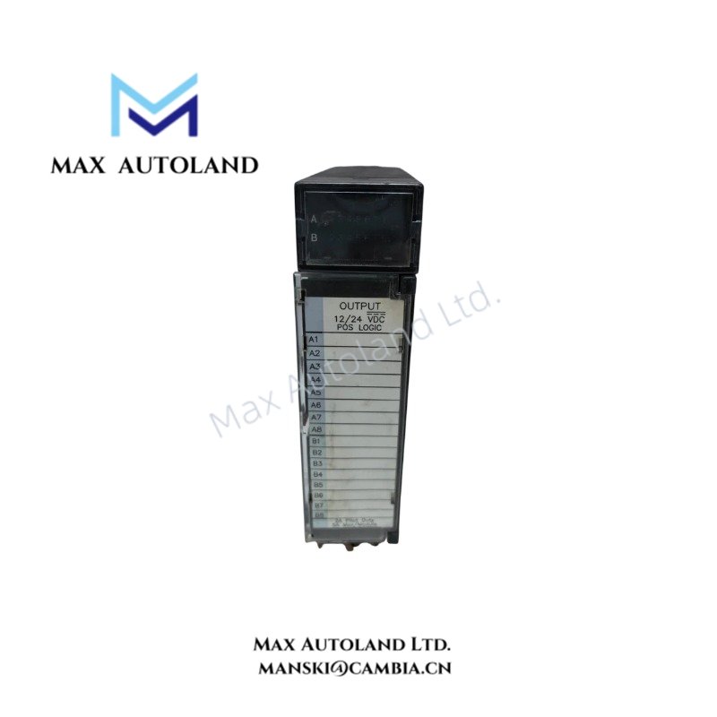
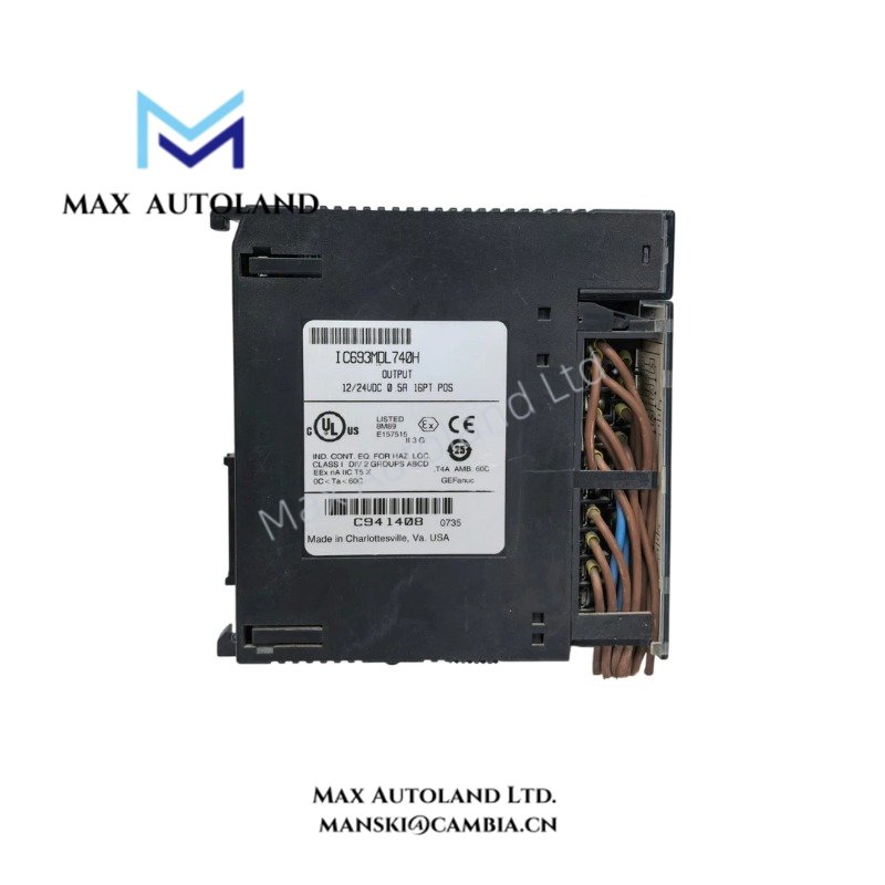
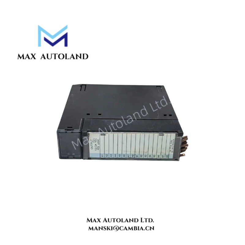
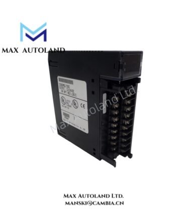
Configured for 12/24 VDC discrete output switching in a Series 90-30 PLC, the General Electric IC693MDL740 (IC693MDL740 Output Module) provides 16 positive-logic output points arranged in two groups.
Hardware Specifications
| Parameter | Specification |
|---|---|
| Model | IC693MDL740 |
| Brand | General Electric |
| Series | Series 90-30 |
| Product Type | Positive Logic Output Module |
| Output Points | 16 |
| Output Groups | 2 groups |
| Channels per Group | 8 channels |
| Output Voltage | 12 to 24 VDC (+20%, -15%) |
| Output Current per Channel | 0.5 A |
| Output Current per Common | 2 A for 10 ms |
| Terminal Type | Screw terminals |
| Operating Temp | 0 to 60 deg C |
| Storage Temp | -40 to 85 deg C |
| Weight | 0.3 kg |
| Dimensions | 3.6 x 13 x 13.5 cm |
| Origin | USA |
PLC Output Switching Characteristics
The IC693MDL740 provides 16 discrete positive-logic outputs for external DC loads. Each group contains eight output channels. The supplied specification limits each channel to 0.5 A and specifies a 2 A common-current value for 10 ms.
The module accepts a 12 to 24 VDC output supply range with a stated tolerance of +20% and -15%. Screw terminals provide the physical connection between the module and field wiring.
For control-panel wiring, separate the output conductors from high-energy AC circuits where practical. Maintain clear terminal identification so each eight-channel group remains associated with its intended field loads.
Frequently Asked Questions
Q: How many output channels does the IC693MDL740 provide?
A: The module provides 16 output points, divided into two groups of eight channels.
Q: What output voltage does the IC693MDL740 support?
A: The specified output voltage range is 12 to 24 VDC, with a tolerance of +20% and -15%.
Q: What is the specified output current per channel?
A: Each output channel supports 0.5 A according to the supplied technical data. The specified common-current value is 2 A for 10 ms.
Field Installation Guidelines
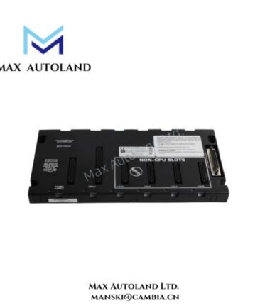
Mount the module in the designated Series 90-30 rack position and secure the associated field wiring at the screw terminals. Verify terminal assignments before applying the DC field supply.
Route DC output wiring separately from high-voltage power conductors where possible. Use appropriate wire insulation and protective devices for the connected load. Keep the terminal area free from loose conductors and ensure each conductor has a firm mechanical connection.
Before energizing the outputs, verify the 12 to 24 VDC supply range, polarity, common connections, and individual load requirements against the control-system drawings. Do not exceed the specified 0.5 A output current per channel.