
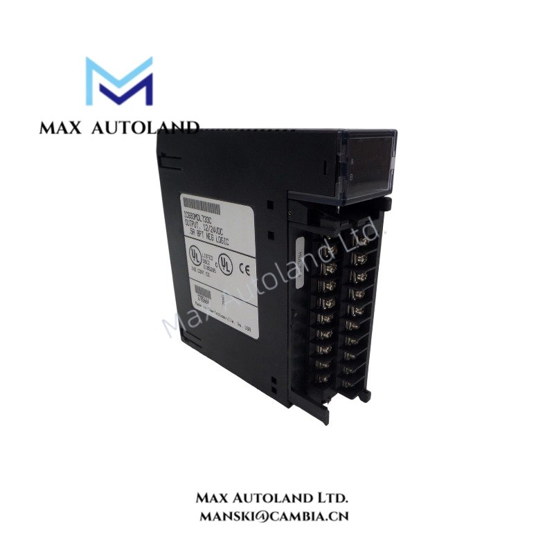
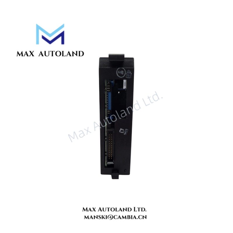
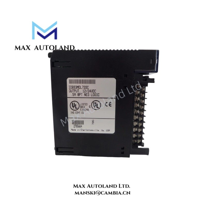
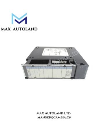
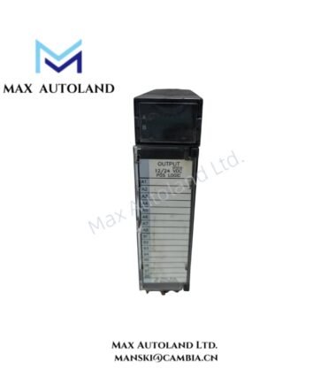
Overview
Configured for discrete DC output switching in the Series 90-30 PLC platform, the GE IC693MDL733 (IC693MDL733 Negative Logic Output Module) provides eight physical output points. Each output supports 12/24 VDC operation with a peak current rating of 0.5 A. The module draws 50 mA from the 5 VDC PLC supply.
Hardware Specifications
| Parameter | Specification |
|---|---|
| Model | IC693MDL733 |
| Brand | General Electric |
| Series | Series 90-30 |
| Module Type | Negative Logic Output Module |
| Product Function | Digital DC Output |
| Number of Outputs | 8 |
| Output Logic | Negative Logic |
| Rated Voltage | 12/24 VDC |
| Peak Current per Output | 0.5 A |
| Module Current Draw | 50 mA |
| Module Voltage Input | 5 VDC |
| Power Consumption | 0.25 W at 5 VDC and 50 mA |
| Origin | USA |
| Weight | 0.36 kg |
| Dimensions | Estimated shipping size: 3.5 x 13 x 13.5 cm |
Negative Logic Output Characteristics
The IC693MDL733 provides eight negative logic output points for discrete DC switching. The field-side output circuit operates at 12/24 VDC, while the PLC module receives its internal supply at 5 VDC.
Each output has a stated peak current capability of 0.5 A. The eight-point configuration provides eight independent discrete output positions within one module. Field wiring should maintain the correct polarity and common reference required by the connected load circuit.
The stated module current draw is 50 mA from the 5 VDC supply. Based on the supplied electrical values, this corresponds to approximately 0.25 W of module-side power consumption.
Frequently Asked Questions
Q: How many output points does the IC693MDL733 provide?
A: The module provides 8 negative logic DC output points.
Q: What voltage does each output support?
A: The specified output voltage is 12/24 VDC.
Q: What is the peak current rating per output?
A: Each output has a specified peak current rating of 0.5 A.
Field Installation Guidelines
- Verify the module position and terminal assignment against the applicable Series 90-30 hardware documentation before wiring.
- Confirm the field supply voltage and polarity before connecting the 12/24 VDC output circuits.
- Keep DC output wiring separate from high-voltage AC conductors and high-current switching conductors where practical.
- Use appropriately rated conductors and terminal hardware for the connected load current.
- Provide suitable external protection for field loads when required by the load circuit design.
- Route signal and power wiring to minimize coupling from contactors, motors, and other switching devices.
- Verify the output common and return connections before applying field power.
- Inspect terminal tightness and wiring polarity during commissioning.
- Do not exceed the specified 0.5 A peak current per output.


