Overview
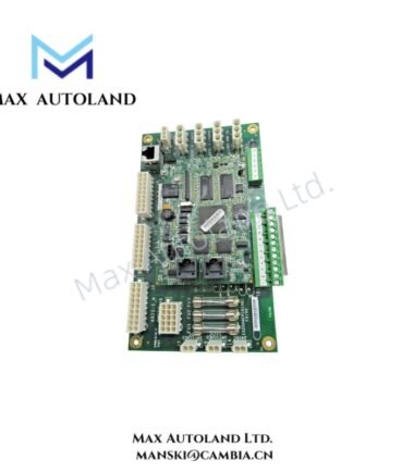
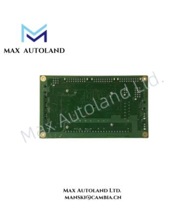
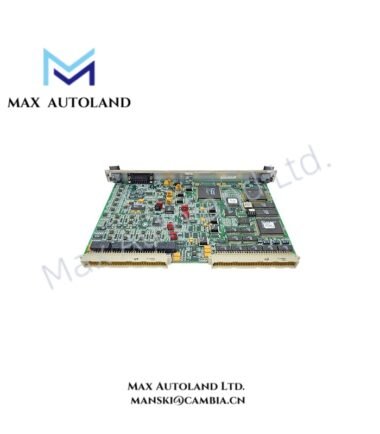
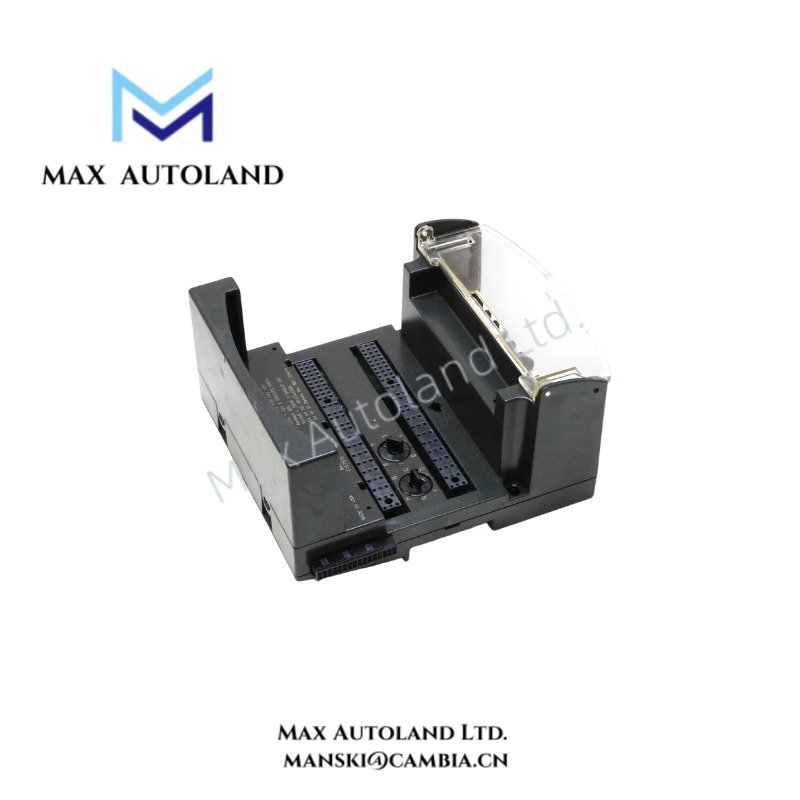
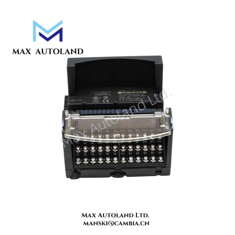
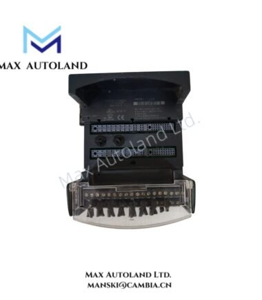
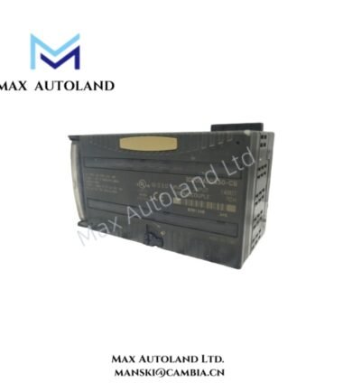
Configured for mounting and terminating local VersaMax I/O modules, the GE Fanuc IC200CHS001 (IC200CHS001 I/O Carrier) provides direct physical and electrical support for field wiring and module installation within VersaMax PLC systems. The carrier uses a horizontal orientation, mounts on a DIN rail, and provides 36 barrier-style terminals for connection to supported I/O circuits.
Hardware Specifications
| Parameter | Specification |
|---|---|
| Model | IC200CHS001 |
| Brand | GE Fanuc |
| Manufacturer | General Electric |
| Series | VersaMax |
| Product Type | I/O Carrier |
| Carrier Type | Local barrier-style, integrated type |
| Orientation | Horizontal |
| Carrier Mounting | DIN rail |
| Barrier-Style Terminals | 36 |
| Max. I/O Points | 32 |
| Max. Voltage Rating | 264 VAC |
| Max. Voltage Transients | 300 VAC |
| Current per Point | Max. 2 A |
| Terminal Torque | 0.37 to 0.5 lb-ft |
| Origin | USA |
| Weight | 0.28 kg |
| Dimensions | 13.8 x 11.5 x 7 cm |
VersaMax I/O Density and Carrier Integration
The IC200CHS001 supports installation arrangements with up to 32 I/O points. Its integrated local carrier construction combines module support and field termination within a single hardware assembly. The 36 barrier-style terminals provide physical connection points for field conductors.
The horizontal carrier mounts directly onto a DIN rail. Therefore, the installation layout can align I/O hardware along the control panel rail while maintaining direct access to terminal connections. The carrier also supports circuit ratings of up to 264 VAC, with transient voltages specified up to 300 VAC.
Frequently Asked Questions
Q: How many I/O points can the IC200CHS001 support?
A: The IC200CHS001 supports a maximum of 32 I/O points.
Q: How is the IC200CHS001 installed in a control panel?
A: The carrier uses DIN rail mounting and installs in a horizontal orientation. The mounting rail and carrier should be securely fixed before installing associated I/O hardware and field wiring.
Q: What is the maximum current rating per point?
A: The specified maximum current is 2 A per point. Field circuits should remain within the applicable electrical ratings of the installed VersaMax I/O modules and the overall system configuration.
Field Installation Guidelines
Mount the IC200CHS001 on a properly secured DIN rail and maintain its specified horizontal orientation. Ensure that the carrier is mechanically locked onto the rail before installing I/O modules.
Terminate field conductors at the 36 barrier-style terminals using suitable wire preparation and the specified terminal torque range of 0.37 to 0.5 lb-ft. Avoid excessive torque because it can damage terminal hardware or affect conductor retention.
Route field wiring separately from high-voltage switching and high-noise power conductors where practical. In addition, apply grounding and shielding practices according to the connected I/O module requirements and the control system wiring design.
Verify conductor identification, circuit voltage, current loading, and module compatibility before energizing the VersaMax station. Disconnect system power before installing or removing carrier-mounted hardware unless the complete system documentation specifically permits the required operation.