Overview
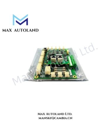
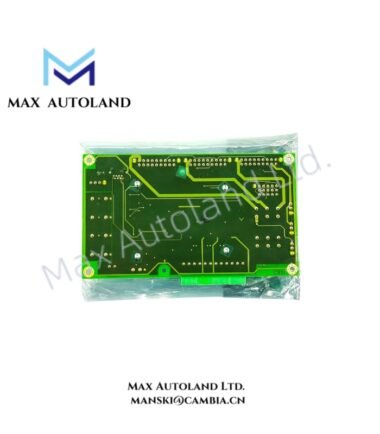
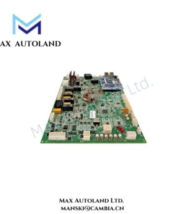
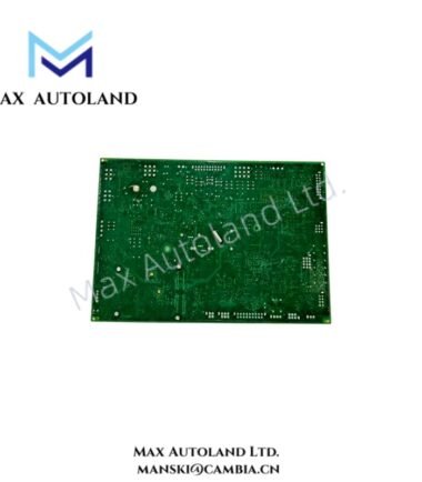
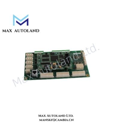
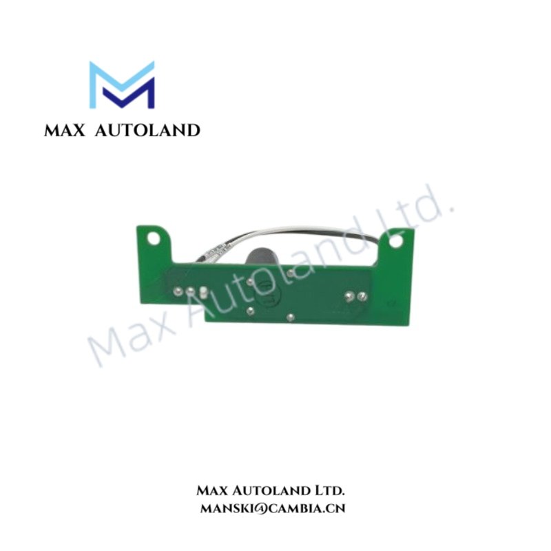
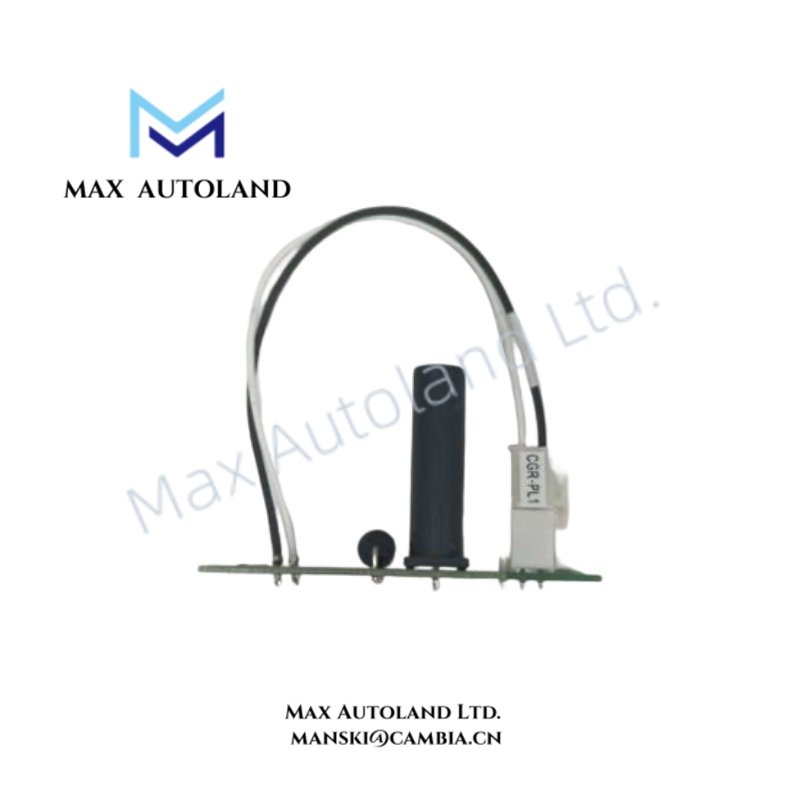
The GE IS200AEPGG1AAA, also cataloged as the IS200AEPGG1A Drive Control Module, operates as a dedicated hardware component for drive command processing and control signal execution within GE Mark VI / Mark VIe control platforms.
Hardware Specifications
| Parameter | Specification |
|---|---|
| Model | IS200AEPGG1AAA |
| Brand | General Electric (GE) |
| Product Type | Drive Control Modules |
| Series | Mark VI / Mark VIe Speedtronic |
| Origin | USA |
| Operating Temp | Industrial control cabinet environment; exact range not specified |
| Power Consumption | Backplane powered; exact consumption not specified |
| Function | Drive control signal processing and hardware interface |
| Mounting Type | Printed circuit board assembly |
| Construction | Surface-mount electronic assembly |
| Configuration Tool | ToolboxST compatible engineering environment |
| Application Interface | Turbine control and industrial drive systems |
Industrial Control Interface and Firmware Compatibility
The GE IS200AEPGG1AAA belongs to the GE Speedtronic Mark VI / Mark VIe hardware family. It processes control commands through the controller backplane and exchanges operational data with associated control modules.
The module supports GE industrial control architectures through firmware-based configuration and hardware identification functions. Therefore, system compatibility depends on the installed controller revision, application firmware, and configured I/O architecture.
The AEPG board design follows GE industrial automation practices for printed circuit assemblies, including controlled signal routing, processor communication interfaces, and diagnostic feedback mechanisms.
Frequently Asked Questions
Q: Does the IS200AEPGG1AAA support hot-swapping during system operation?
A: The module hot-swap capability depends on the installed Mark VI / Mark VIe rack configuration. Operators should follow GE shutdown and replacement procedures before removing the board.
Q: Which engineering software is used for configuration and diagnostics?
A: The module integrates with GE ToolboxST engineering software when installed within compatible Mark VI / Mark VIe control systems.
Q: What installation practices are required for electrical connections?
A: Installation requires correct rack seating, proper grounding, controlled cable routing, and verification of connector alignment before system energization.
Field Installation Guidelines
- Install the IS200AEPGG1AAA in the designated GE control rack slot specified by the system hardware configuration.
- Verify that the backplane connector is clean and fully engaged before applying power.
- Maintain separation between control signal wiring and high-voltage power cables to reduce electrical interference.
- Connect cabinet grounding according to industrial control panel standards.
- Confirm firmware compatibility and hardware identification through the engineering workstation before commissioning.
- Use approved anti-static handling procedures when removing or installing the circuit board assembly.