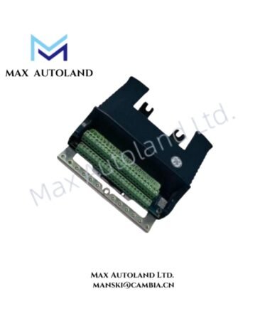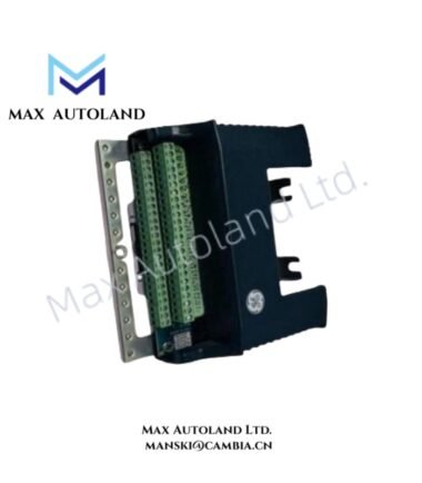
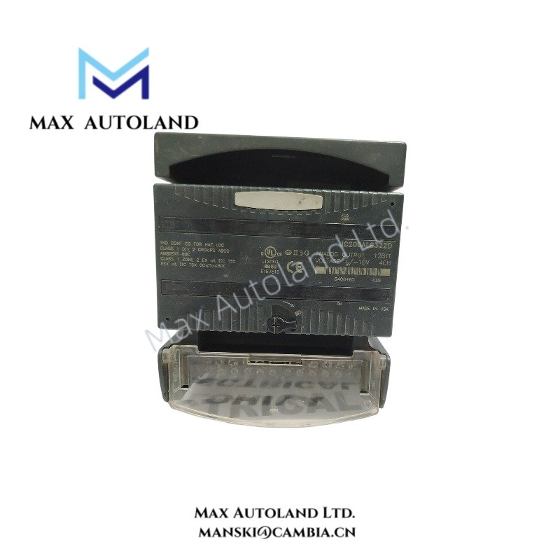
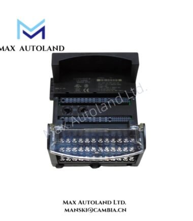
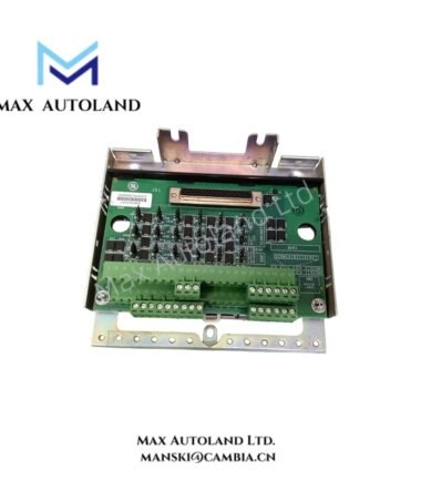
Overview
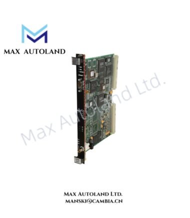
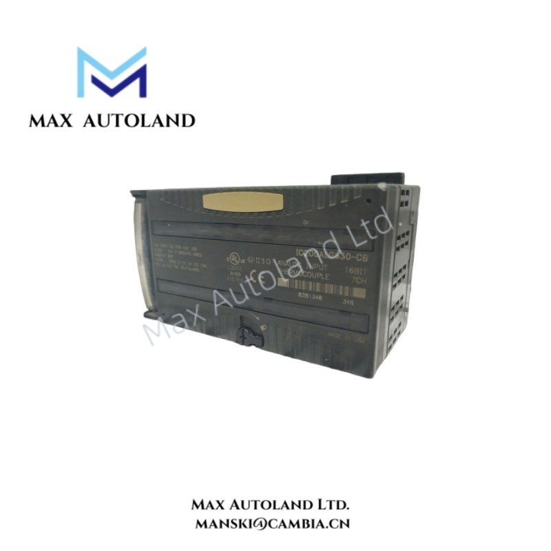
Configured for converting controller data into analog voltage signals in VersaMax PLC systems, the GE Fanuc IC200ALG322 (IC200ALG322 Analog Voltage Output Module) provides direct physical and electrical signal execution. The module supplies four single-ended analog output channels in one group, with an output range of +/- 10.24 VDC. It exchanges module data through the VersaMax backplane and uses external field power for analog output operation.
Hardware Specifications
| Parameter | Specification |
|---|---|
| Model | IC200ALG322 |
| Brand | GE Fanuc |
| Series | VersaMax |
| Module Type | Analog Voltage Output Module |
| Number of Channels | 4 channels |
| Channel Configuration | Single-ended, one group |
| Output Voltage Range | +/- 10.24 VDC |
| Resolution | 12-bit |
| Output Resolution | 5 mV or 16 counts |
| Update Rate | 0.3 ms maximum per module |
| Resistive Load | 5000 ohms minimum |
| Capacitive Load | 1.0 uF maximum |
| Accuracy at 25 deg C | +/- 0.3% of full scale, typical |
| Maximum Accuracy | +/- 1% over operating range |
| External Field Power | +18 to +30 VDC including ripple |
| Backplane Power Consumption | 50 mA maximum from +5 V bus |
| Isolation | 250 VAC continuous |
| Dielectric Withstand | 1500 VAC for 1 minute |
| Channel-to-Channel Crosstalk Rejection | 70 dB minimum |
| Status Indicators | OK green, FLD PWR green |
| Power Consumption | 50 mA maximum from +5 V backplane bus; external field power +18 to +30 VDC |
VersaMax Backplane Communication and I/O Density
The IC200ALG322 operates through the VersaMax backplane, where controller data transfers to the analog output circuitry for voltage signal generation. The module occupies a single modular position within the VersaMax I/O arrangement.
The four-channel configuration supports I/O density scaling without requiring separate output hardware for each voltage signal. In addition, the module monitors backplane power through the OK indicator and field power through the FLD PWR indicator. Therefore, installation personnel can distinguish between internal module power status and external field supply availability during commissioning.
The module also provides configurable output behavior during communication or backplane power interruptions. Depending on the configured operating behavior, outputs can hold their last state or move to assigned default values.
Frequently Asked Questions
Q: What voltage signals does the IC200ALG322 generate?
A: The IC200ALG322 provides four analog voltage output channels with an output range of +/- 10.24 VDC.
Q: What power does the module require?
A: The module draws up to 50 mA from the +5 V VersaMax backplane bus and requires an external field power supply of +18 to +30 VDC, including ripple.
Q: What load limits apply to the analog outputs?
A: Each output supports a resistive load of at least 5000 ohms and a capacitive load of up to 1.0 uF.
Field Installation Guidelines
Mount the IC200ALG322 in a compatible VersaMax I/O carrier and confirm that the backplane connection is fully engaged before applying power.
Connect the external field power supply within the specified +18 to +30 VDC range. Verify the FLD PWR indicator after energizing the field supply and verify the OK indicator for backplane power status.
Route analog output wiring separately from high-current switching conductors, motor leads, and other electrical noise sources. Where shielded cable is required by the field installation design, terminate the cable shield according to the system grounding arrangement.
Check connected field device input impedance before commissioning to ensure that the analog output load remains within the specified resistive and capacitive limits. Finally, verify each output channel against the configured controller value during system startup.