
Overview
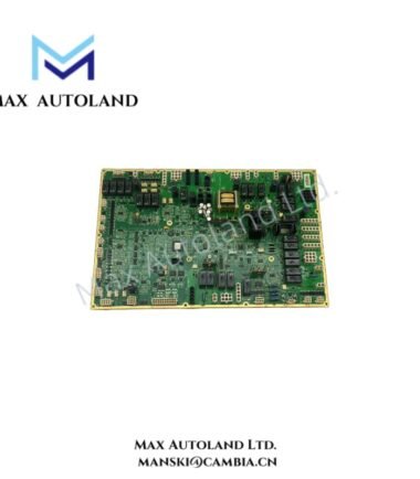
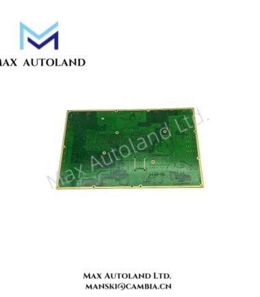
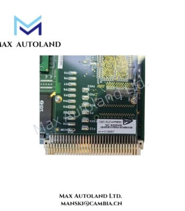
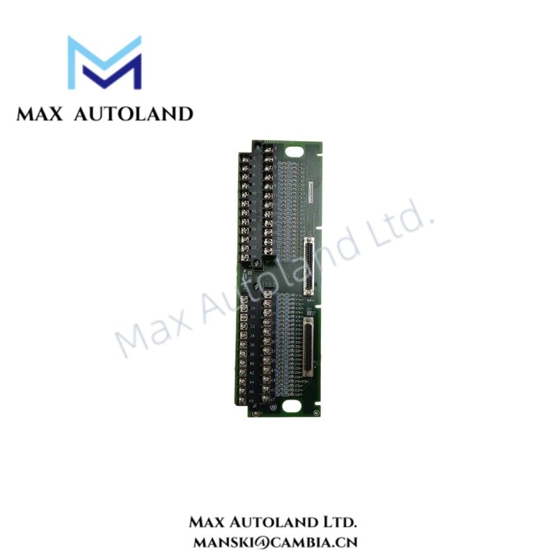
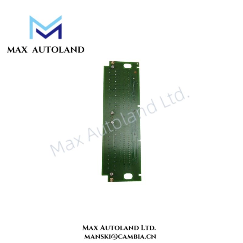
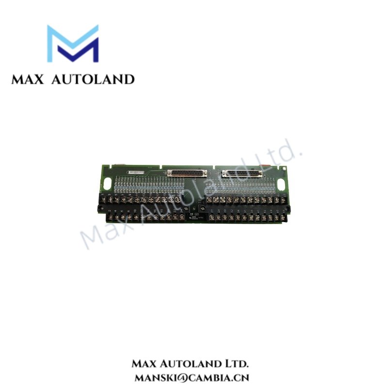
Configured for thermocouple signal termination in the GE Mark VI control system, the GE IS200TBTCH1CBB (IS200TBTCH1C Thermocouple Input Terminal Board) provides direct electrical termination for 24 thermocouple input channels. It supports E, J, K, S, and T thermocouple types and operates from a 24 VDC supply environment.
Hardware Specifications
| Parameter | Specification |
|---|---|
| Model | IS200TBTCH1CBB |
| Spare Model | IS200TBTCH1C |
| Brand | General Electric |
| Product Type | Thermocouple Input Terminal Board |
| Series | Mark VI |
| System | SPEEDTRONIC Mark VI |
| Board Type | Type 6 |
| Number of Channels | 24 |
| Thermocouple Types | E, J, K, S, T |
| Voltage | 24 VDC |
| Operating Temp | 0 deg C to +45 deg C |
| Weight | 0.52 kg |
| Origin | USA |
| Dimensions | Shipping size: 33 x 10.2 x 4.5 cm |
| Replacement Module | TBCIH2C |
| Tariff Code | 8537101190 |
| Manufacturer | General Electric |
Thermocouple Input Signal Handling
The IS200TBTCH1CBB provides the termination interface for 24 thermocouple input channels within the Mark VI system. The board accepts E, J, K, S, and T thermocouple types.
Because thermocouple signals operate at low voltage levels, field wiring should maintain proper polarity and avoid routing alongside high-current or high-voltage conductors. In addition, the selected thermocouple type must match the configured input channel and associated control-system settings.
The supplied specifications identify the board as a Type 6 thermocouple input terminal board. They do not specify individual channel isolation, cold junction compensation circuitry, or input accuracy; therefore, those parameters should be confirmed against the applicable GE Mark VI hardware documentation before system commissioning.
Frequently Asked Questions
Q: How many thermocouple input channels does the IS200TBTCH1CBB provide?
A: The supplied specification identifies 24 thermocouple input channels.
Q: Which thermocouple types are supported?
A: The specified thermocouple types are E, J, K, S, and T.
Q: What operating temperature range is specified for this board?
A: The supplied data specifies 0 deg C to +45 deg C.
Field Installation Guidelines
- Verify the board identification and terminal assignment before installation.
- Confirm that the connected thermocouple type matches the configured input channel.
- Maintain correct thermocouple polarity throughout the field wiring circuit.
- Route thermocouple wiring separately from high-voltage and high-current conductors where practical.
- Use suitable thermocouple extension or compensating wire for the selected thermocouple type.
- Inspect terminal connections for secure mechanical contact before energizing the control system.
- Apply appropriate cable shielding and grounding practices according to the Mark VI installation documentation.
- Verify the ambient temperature remains within the specified 0 deg C to +45 deg C range.
- Confirm replacement-board compatibility before substituting the IS200TBTCH1CBB with the listed TBCIH2C replacement module.
- Do not infer unspecified power consumption, channel isolation, accuracy, or compensation characteristics without the applicable hardware manual.