
Overview
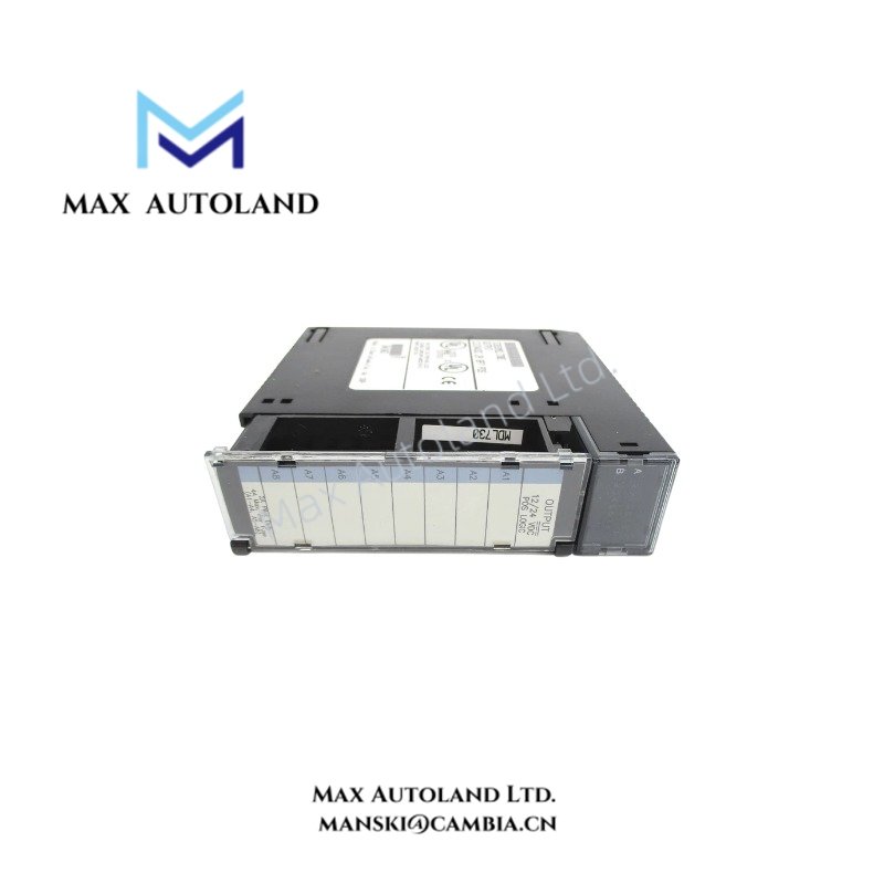
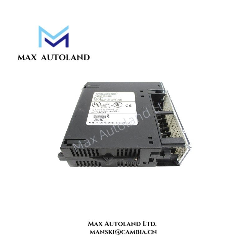
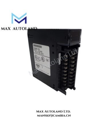
Configured for discrete DC load switching in the Series 90-30 PLC system, the GE IC693MDL730 (IC693MDL730 Positive Logic Output Module) provides eight isolated output points for 12/24 VDC field circuits. Each point supports up to 2 A, while the module provides 1500 V isolation between the field side and logic side.
Hardware Specifications
| Parameter | Specification |
|---|---|
| Model | IC693MDL730 |
| Brand | General Electric (GE) |
| Series | Series 90-30 |
| Product Type | Positive Logic Output Module |
| Origin | USA |
| Weight | 0.36 kg |
| Dimensions | Estimated shipping size: 3.5 x 13 x 13.5 cm |
| Rated Voltage | 12/24 VDC |
| Output Voltage Range | 12 to 24 VDC |
| Outputs per Module | 8 |
| Output Current | 2 A maximum per point |
| Isolation | 1500 V between field side and logic side |
| Inrush Current | 9.4 A for 10 ms |
| Output Voltage Drop | 1.2 V maximum |
| Off-state Leakage | 1 mA maximum |
| On Response Time | 2 ms maximum |
| Off Response Time | 2 ms maximum |
Discrete Output Switching Characteristics
The IC693MDL730 uses positive-logic output switching for 12/24 VDC field circuits. Therefore, the output stage sources current to the connected load when the corresponding logic point turns on. Each of the eight output points supports a maximum current of 2 A.
The output stage has a maximum voltage drop of 1.2 V under the specified output condition. In addition, off-state leakage remains at a maximum of 1 mA. The specified 2 ms maximum on and off response times define the electrical switching response of each output point.
The module also provides 1500 V isolation between the field side and logic side. This isolation separates the field wiring from the PLC logic interface and limits direct electrical coupling between these sections.
Frequently Asked Questions
Q: How many output points does the IC693MDL730 provide?
A: The module provides 8 DC output points.
Q: What load current can each output point handle?
A: Each output point supports a maximum output current of 2 A.
Q: What isolation does the module provide?
A: The supplied specifications state 1500 V isolation between the field side and logic side.
Field Installation Guidelines
Install the IC693MDL730 in the applicable Series 90-30 PLC rack according to the system hardware arrangement. Confirm that the field circuit voltage matches the specified 12 to 24 VDC output range before connecting loads.
Route DC field wiring separately from high-voltage AC wiring and high-current conductors where practical. Secure each conductor at the terminal point and maintain clear identification for all eight output circuits.
Connect the field-side wiring according to the positive-logic output arrangement. Verify load polarity before energizing the circuit. Also check that the connected load does not exceed the 2 A maximum current specified for an individual output point.
For shielded field cables, terminate the shield according to the site’s grounding and EMC practices. Before commissioning, inspect wiring polarity, terminal tightness, load current, and PLC point addressing. Finally, test each output point individually and confirm the expected load response.


