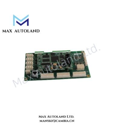



Overview
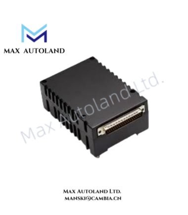
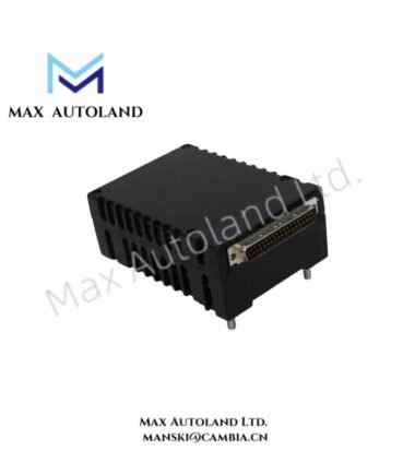
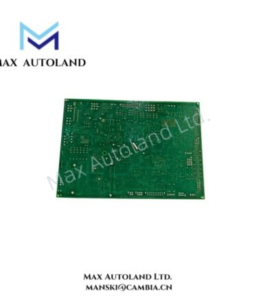
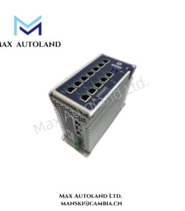
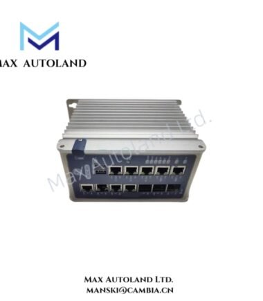
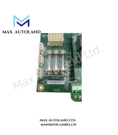
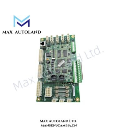
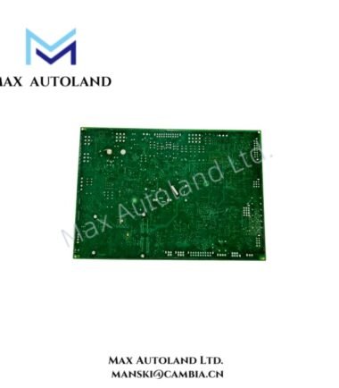
The GE IS215REBFH1A, also cataloged as the IS215REBFH1A Relay Output Board, operates as a dedicated hardware component for relay-based switching execution within the GE Mark VI / Mark VIe Speedtronic control system. The board provides electrical interface channels for external control circuits through relay output contacts.
Hardware Specifications
| Parameter | Specification |
|---|---|
| Model | IS215REBFH1A |
| Brand | General Electric (GE) |
| Origin | USA |
| Product Type | Relay Output Board |
| Series | Mark VI / Mark VIe Speedtronic |
| Board Function | Relay-based digital output interface |
| Input Power | +24 VDC |
| Output Configuration | Multiple relay output channels, dry contact type |
| Weight | Approx. 1.0 kg |
| Dimensions | Approx. 16 cm x 16 cm x 12 cm |
| Operating Temp | -40 deg C to +70 deg C |
| Storage Temp | -55 deg C to +85 deg C |
| Operating Humidity | 5% to 95% RH, non-condensing |
| Power Consumption | Not specified; depends on relay activation load and system configuration |
GE Industrial Control Interface Characteristics
The IS215REBFH1A functions within the GE Mark VI / Mark VIe hardware architecture and exchanges control signals through the system backplane interface. The relay output circuits provide discrete switching paths for external devices, while the board design supports I/O density scaling across turbine control configurations.
Additionally, GE Speedtronic platforms use structured firmware and hardware compatibility management to maintain module identification, configuration recognition, and system-level communication. The IS215REBFH1A integrates with the controller rack through the Mark VIe hardware framework and follows the defined I/O addressing structure.
Frequently Asked Questions
Q: What type of signals does the IS215REBFH1A process?
A: The IS215REBFH1A processes discrete relay output signals and provides dry contact switching interfaces for connected external circuits.
Q: Does the IS215REBFH1A support hot-swapping during system operation?
A: Hot-swap capability depends on the installed Mark VI / Mark VIe rack configuration and system procedures. Field replacement should follow GE hardware maintenance requirements.
Q: What installation factors should be considered for this relay output board?
A: Installation should consider correct rack seating, terminal wiring verification, grounding practices, and separation between control wiring and high-voltage circuits.
Field Installation Guidelines
- Verify the module part number before installation into the Mark VI / Mark VIe rack assembly.
- Confirm that the rack power supply is isolated according to site maintenance procedures before removing or installing the board.
- Inspect connector pins and backplane interfaces for contamination, mechanical damage, or oxidation.
- Route relay output wiring separately from high-energy power conductors to reduce electrical interference.
- Connect shielding and grounding according to the plant control cabinet grounding design.
- Verify external relay contact wiring before applying system power and enabling control logic.