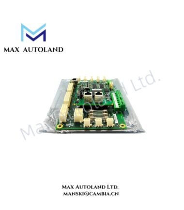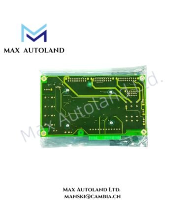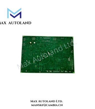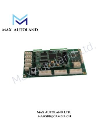

Overview
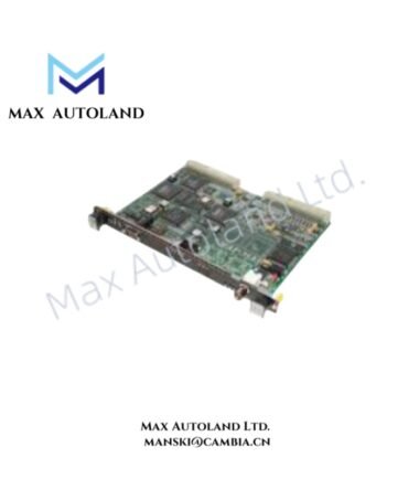
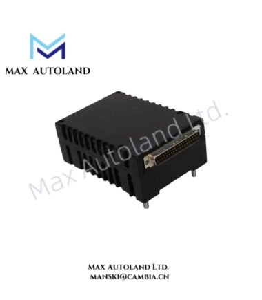
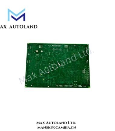
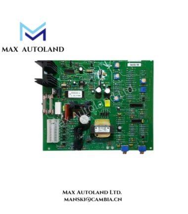
Configured for discrete relay switching in the GE Mark VI / Mark VIe control architecture, the GE IS200ERQCH1A (IS200ERQCH1A Relay Output Module) provides 16 isolated Form C relay outputs for external field circuits. The contacts switch connected loads without directly exposing the control logic to the field circuit.
Hardware Specifications
| Parameter | Specification |
|---|---|
| Model | IS200ERQCH1A |
| Brand | GE / General Electric |
| Product Type | Relay Output Module |
| Series | Mark VI / Mark VIe |
| Weight | Approximately 0.95 kg |
| Dimensions | 241 mm H x 45 mm W x 229 mm D |
| Operating Temp | 0 deg C to 60 deg C |
| Storage Temp | -40 deg C to 85 deg C |
| Relative Humidity | 5% to 95%, non-condensing |
| Power Consumption | Not specified in supplied data |
| Output Type | Form C electromechanical relay contacts |
| Number of Outputs | 16 |
| Contact Rating | 2 A at 30 VDC / 250 VAC, resistive load |
| Switching Voltage | Up to 250 VAC / 30 VDC |
| Dielectric Strength | 1500 VAC between contacts and logic |
Relay Output and Electrical Isolation
The IS200ERQCH1A uses electromechanical Form C relay contacts to provide discrete switching paths. Each output can interface the Mark VI / Mark VIe control logic with an external field circuit.
The relay contacts support switching up to 2 A at 30 VDC or 250 VAC for resistive loads, according to the supplied specifications. Therefore, the connected load and its electrical characteristics must remain within the stated contact rating.
The specified 1500 VAC dielectric strength separates the relay contact circuit from the logic side. However, installation must still maintain appropriate clearance, insulation, and wiring practices for the applied field voltage.
Frequently Asked Questions
Q: How many relay outputs does the IS200ERQCH1A provide?
A: The module provides 16 relay output channels using Form C electromechanical contacts.
Q: What field voltage can the relay contacts switch?
A: The supplied specification states up to 250 VAC or 30 VDC, with a 2 A rating for resistive loads.
Q: Does the supplied data specify power consumption?
A: No. The available specifications do not provide a power-consumption value, so no numerical value should be assumed.
Field Installation Guidelines
Mount the module according to the applicable Mark VI / Mark VIe rack and cabinet arrangement. Confirm the board orientation and mechanical retention before connecting field wiring.
Separate relay wiring from low-level signal wiring where practical. Maintain appropriate physical clearance between circuits operating at different voltage levels.
Use wiring, terminals, and protective devices rated for the connected field voltage and load current. Verify polarity for DC circuits and verify the switching circuit configuration before energization.
For inductive loads such as solenoids and contactors, apply suitable external suppression according to the load manufacturer’s requirements. This reduces contact arcing and limits transient voltage at relay switching points.
Before commissioning, verify each relay contact state against the control logic and field-device wiring. Do not exceed the specified 2 A resistive-load rating or the stated 250 VAC / 30 VDC switching limits.