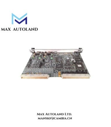
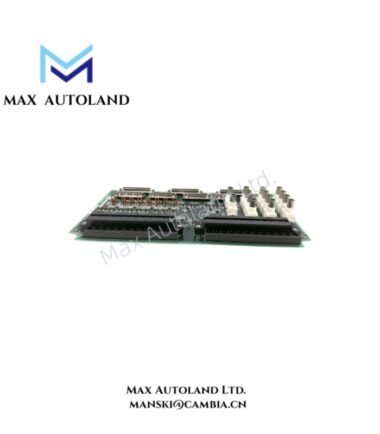
Overview
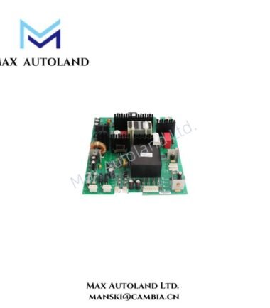
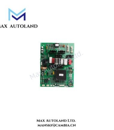
Configured for AC voltage and current feedback processing in the EX2100 / EX2100E Excitation Control System, the GE IS200EACFG1BAA (IS200EACFG1B Exciter AC Feedback Board) conditions exciter feedback signals for the excitation regulator. The board uses onboard transformers, resistive networks, capacitors, and configuration jumpers to process the connected AC feedback circuits.
Suffix Breakdown & Model Matrix
The supplied documentation identifies IS200EACFG1BAA as the full board designation and IS200EACFG1B as the base designation. The supplied data does not define each suffix position independently, so no additional suffix interpretation is assigned.
Hardware Specifications
| Parameter | Specification |
|---|---|
| Model | IS200EACFG1BAA |
| Base Model | IS200EACFG1B |
| Brand | GE / General Electric |
| Product Type | Exciter AC Feedback Board |
| Product Series | EX2100 / EX2100E Excitation Control System |
| System Architecture | Mark VI / Mark VIe Speedtronic |
| Group Designation | G1 |
| Functional Revision | B |
| Input Voltage | Up to 480 Vrms |
| Voltage Range | +20% |
| Frequency | 50/60 Hz |
| Maximum Cable Length | 90 m |
| Feedback Components | T1, T2, T3, T4 voltage/current transformers |
| Configuration | Jumpers including J504, J509, J514 |
| Board Protection | Conformal coating |
AC Feedback Signal Processing
The IS200EACFG1BAA processes AC voltage and current feedback associated with the exciter circuit. The onboard transformers provide the interface for the specified AC feedback paths, while resistor and capacitor networks establish the associated signal-conditioning circuits.
The supplied input specification supports voltages up to 480 Vrms with a +20% voltage range and 50/60 Hz operation. Therefore, the connected feedback circuit must match the applicable EX2100 / EX2100E configuration before energization.
The board also contains configuration jumpers, including J504, J509, and J514. These components form part of the board configuration and should remain consistent with the applicable system documentation.
Because the board belongs to a GE excitation-control platform, its physical signal path remains separate from higher-level turbine-control communication functions. The EACF hardware processes electrical feedback locally before the regulator uses the resulting feedback information.
Frequently Asked Questions
Q: What type of signals does the IS200EACFG1BAA process?
A: It processes AC voltage and current feedback associated with the exciter circuit.
Q: What AC input range is specified for this board?
A: The supplied data specifies input voltage up to 480 Vrms, with a +20% voltage range at 50/60 Hz.
Q: What cable length is specified for the feedback connection?
A: The supplied specification states a maximum cable length of 90 m. The actual installation should follow the applicable EX2100 / EX2100E system documentation.
Field Installation Guidelines
Install the board in the designated EX2100 / EX2100E hardware location and secure it according to the applicable rack or mounting arrangement.
Before wiring, isolate the excitation system and verify that the connected AC feedback circuits are de-energized. Confirm the feedback source, terminal assignment, and circuit identification against the system drawings.
Route AC feedback wiring separately from low-level control and communication wiring where practical. Avoid unnecessary parallel routing with high-current switching conductors to reduce unwanted electrical coupling.
Inspect the board, transformer components, jumpers, and connectors before installation. Do not alter configuration jumpers such as J504, J509, or J514 without confirming the required system configuration.
Keep the feedback cable length within the supplied 90 m maximum. Use appropriately rated wiring and maintain the required insulation and clearance for the connected AC voltage.
After installation, verify all terminations before applying excitation power. Check the expected feedback signal at the designated measurement points and confirm that the regulator receives the correct AC feedback before returning the system to service.