

Overview
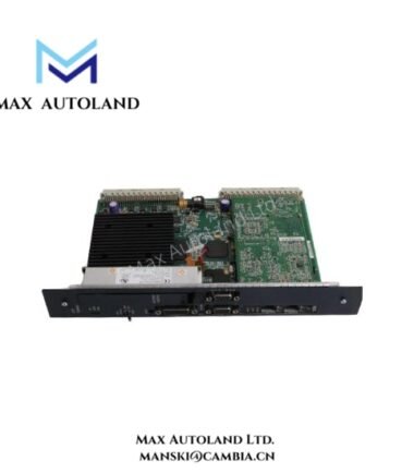
Configured for 100 Mbps network communication in an RX3i PACSystems controller, the GE Fanuc Emerson IC695SPF002 (IC695SPF002 scanner module) provides network connectivity through two RJ-45 ports and two SFP cages. The module supports multi-mode fiber links with a specified reach of 2 km and supports an SD card.
Hardware Specifications
| Parameter | Specification |
|---|---|
| Model | IC695SPF002 |
| Brand | GE Fanuc Emerson |
| Product Line | RX3i PACSystems |
| Product Type | Scanner Module |
| Weight | 0.19 lbs (0.09 kg) |
| Operating Temp | 0 to 60 deg C |
| Power Consumption | Not specified |
| Power Requirement | 3.3 to 5 V |
| Communication Speed | 100 Mbps |
| Fiber Type | Multi-mode fiber (MMF) |
| Fiber Link Length | 2 km |
| Port Connectors | Two RJ-45 and two SFP cages |
| SD Card | Supported |
| LED Indicators | Yes |
Network Interface and Physical Connectivity
The IC695SPF002 provides two RJ-45 interfaces and two SFP cages. Therefore, the module supports both copper and pluggable optical interface connections at the specified 100 Mbps communication speed.
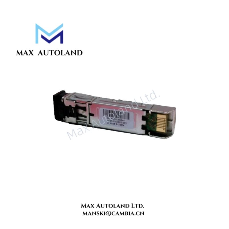
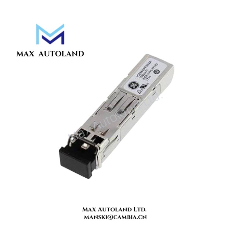
The specified fiber medium is multi-mode fiber (MMF), with a maximum stated link length of 2 km. In addition, the SFP cages allow the applicable optical interface hardware to connect through the module’s pluggable interface positions.
The module also provides LED indicators for local hardware and communication status monitoring. An SD card is supported for the functions defined by the applicable RX3i PACSystems system configuration.
Frequently Asked Questions
Q: What network speed does the IC695SPF002 support?
A: The specified communication speed is 100 Mbps.
Q: What physical network interfaces does the IC695SPF002 provide?
A: The module provides two RJ-45 ports and two SFP cages.
Q: What fiber type and link length are specified for the module?
A: The specified fiber medium is multi-mode fiber (MMF), with a link length of 2 km.
Field Installation Guidelines
Install the IC695SPF002 in the designated RX3i PACSystems hardware configuration and follow the applicable rack and module installation procedures. Before wiring, verify that the supply voltage matches the specified 3.3 to 5 V requirement.
Route communication cables separately from high-voltage power wiring and high-current switching conductors where practical. Maintain appropriate cable bend radii and avoid mechanical stress at the RJ-45 and SFP connections.
For MMF connections, inspect optical connectors before installation and keep connector surfaces clean. Secure each cable to prevent movement or excessive loading on the interface.
Connect the protective and functional grounding conductors according to the controller installation requirements. Finally, verify the LED indications and network link status after installation before placing the communication interface into normal service.