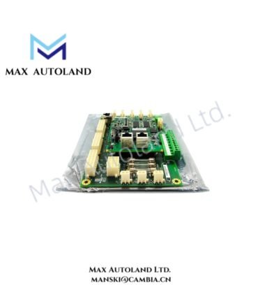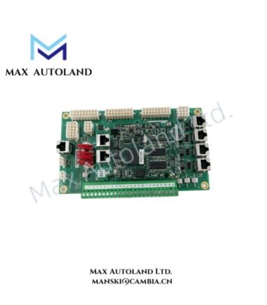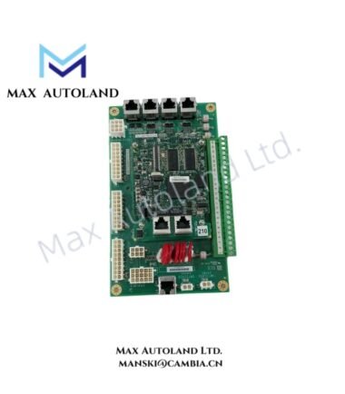
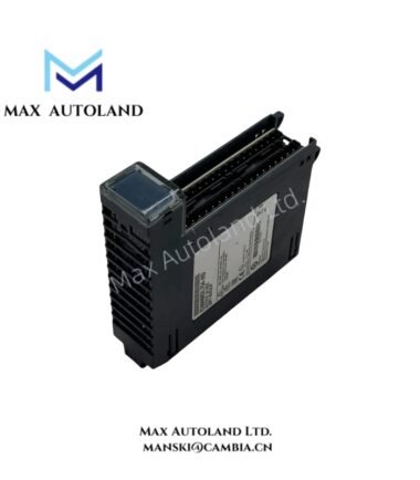
Overview
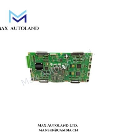
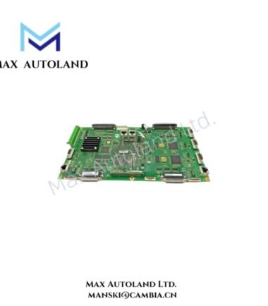
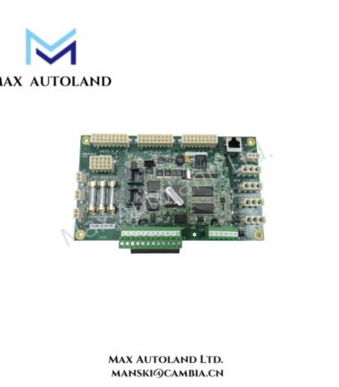
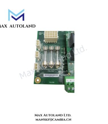
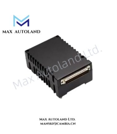
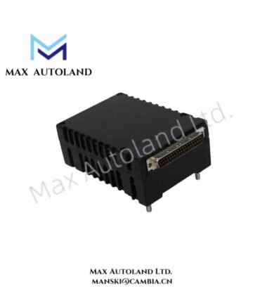
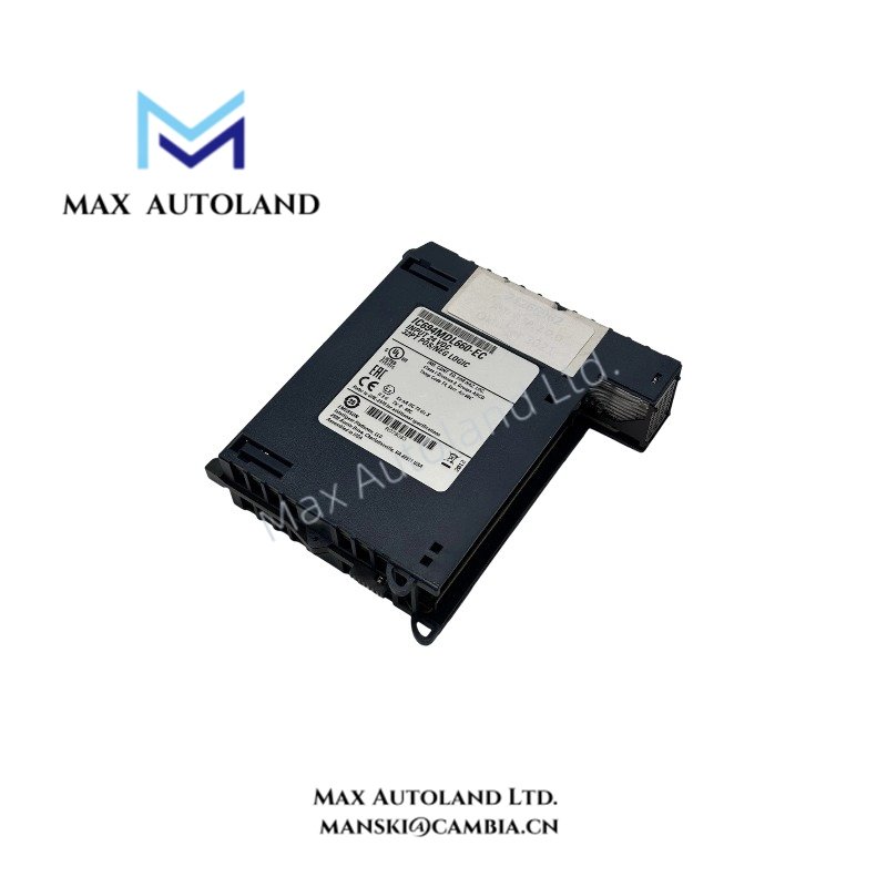
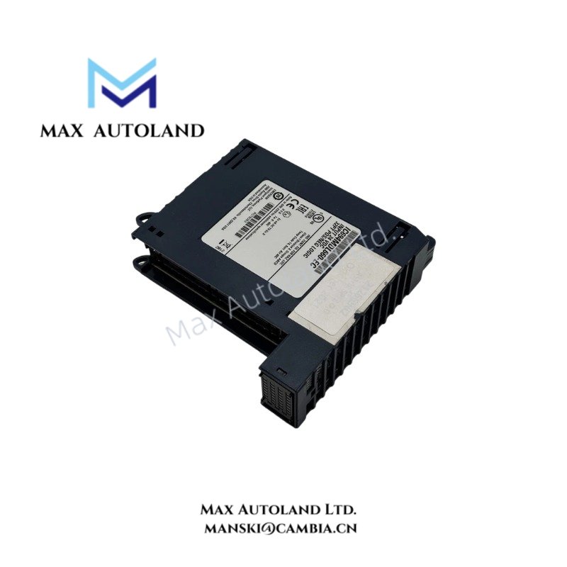
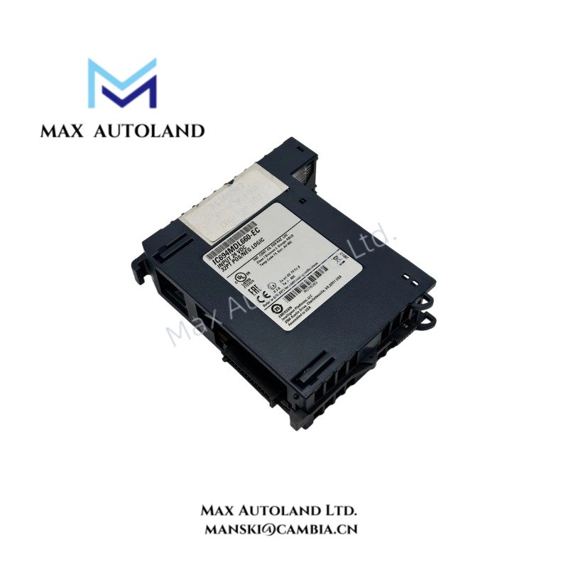
Configured for 24 VDC discrete signal acquisition in the GE Series 90-30 PLC system, the General Electric IC694MDL660 (IC694MDL660 Discrete Input Module) provides 32 input points through the serial bus interface. The module requires a terminal block for field wiring and supports selectable input filter times.
Hardware Specifications
| Parameter | Specification |
|---|---|
| Model | IC694MDL660 |
| Brand | General Electric |
| Module Type | Discrete Input Module |
| Input Voltage | 24 VDC |
| Input Points | 32 |
| Bus Interface | Serial bus |
| Terminal Block | Required |
| Weight | 0.22 kg |
| Dimensions | 3.5 x 13.3 x 13.6 cm |
| Power Consumption | 195 mA @ 5 VDC; 224 mA @ 24 VDC |
| Maximum Inrush Current | 4.78 A for 10 ms |
| Isolation | 250 V AC and 1500 V AC per minute |
| Input Filter Times | 0.5 ms, 1.0 ms, 2.0 ms, 5 ms, 10 ms, 50 ms, 100 ms |
| Response Time | Depends on selected filter time |
| Diagnostics | Terminal block reports diagnostic information to CPU |
| Tariff Code | 8537101190 |
| Country of Origin | USA |
| Place of Shipment | Xiamen, China |
PLC Serial Bus and I/O Signal Handling
The IC694MDL660 accepts 24 VDC discrete field signals across 32 input points. The module transfers input status through its serial bus connection to the PLC control system. The selected input filter determines how the module processes changes on each input.
The available filter settings range from 0.5 ms to 100 ms. Therefore, the configured filter value directly affects the module’s input response behavior. The terminal block also provides a diagnostic reporting path to the CPU.
Frequently Asked Questions
Q: How many discrete input points does the IC694MDL660 provide?
A: The module provides 32 discrete input points for 24 VDC signals.
Q: Does the IC694MDL660 require a terminal block?
A: Yes. The supplied specification states that the module requires a terminal block for field connection and diagnostic reporting to the CPU.
Q: How does the input filter affect response time?
A: The response time depends on the selected filter setting. Available values are 0.5 ms, 1.0 ms, 2.0 ms, 5 ms, 10 ms, 50 ms, and 100 ms.
Field Installation Guidelines
Install the IC694MDL660 in the specified PLC rack and connect the required terminal block before applying field signals. Verify the 24 VDC signal wiring against the control-system drawings.
Route discrete signal wiring separately from high-voltage and high-current conductors where practical. Keep signal wiring secure and avoid unnecessary parallel runs with power cables.
Check terminal polarity and field wiring before energizing the module. Select the input filter according to the required field signal response characteristics. A longer filter time can suppress shorter signal transitions, while a shorter setting permits faster input-state recognition.
Confirm the module’s isolation requirements and maintain the specified electrical separation between field circuits and other wiring. Use the terminal block’s diagnostic reporting path to the CPU when checking input or wiring conditions.