Overview
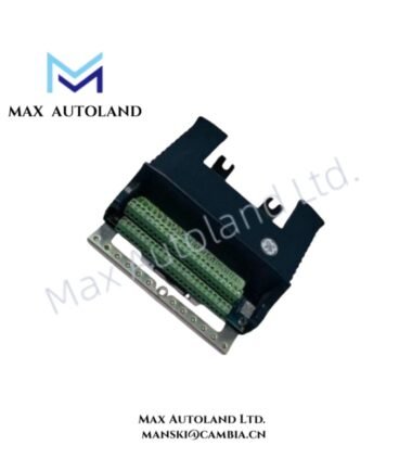
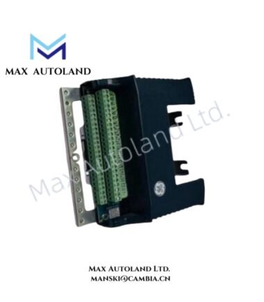
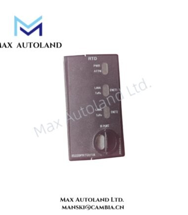
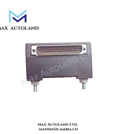
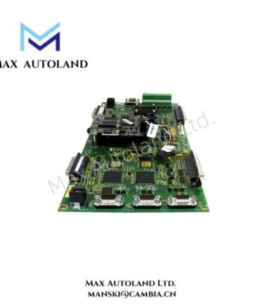
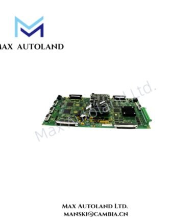
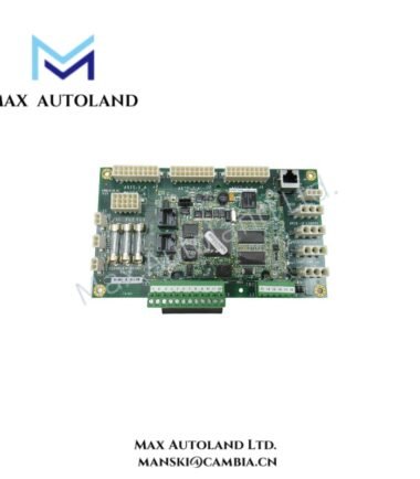
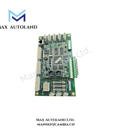
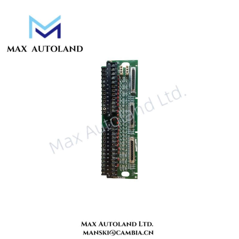
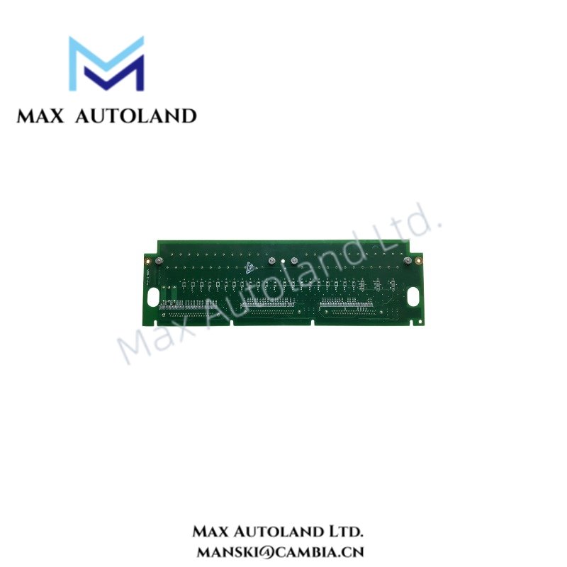
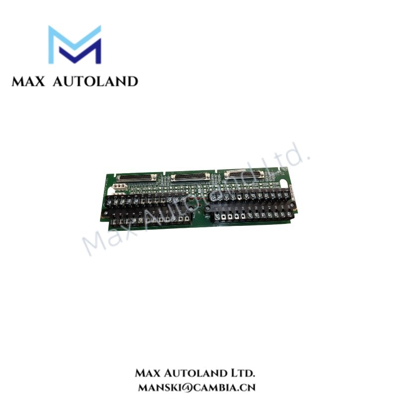
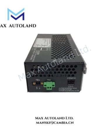
Configured for DC battery power distribution and floating-bus voltage feedback in the Mark VIe turbine control system, the GE IS200JPDEG1AAA (IS200JPDEG1 DC Battery Power Distribution Board) distributes DC supply power to connected terminal boards and system loads. The JPDE uses a floating DC bus referenced to earth through resistors, while the PPDA I/O pack provides voltage feedback for system ground-fault detection.
Hardware Specifications
| Parameter | Specification |
|---|---|
| Model | IS200JPDEG1AAA |
| Base Model | IS200JPDEG1 |
| Brand | General Electric (GE) |
| Series | Mark VIe |
| Product Type | DC Battery Power Distribution Board (JPDE) |
| Origin | USA |
| Dimensions | 16.51 cm high x 17.08 cm wide |
| Operating Temp | 0 deg C to 60 deg C |
| Power Consumption | Not specified in the provided data |
| Number of Channels | 24 |
| Input Voltage Range | 18 VDC to 32 VDC |
| Supported DC System | 24 VDC or 48 VDC setups |
| Input Isolation | 1500 V AC |
| AC Voltage Rejection | 60 V RMS |
| Mounting Type | DIN-rail / vertical base mounting on a metal cabinet bracket |
| Technology | Surface Mount Technology (SMT) |
| Compatible I/O Pack | PPDA |
| Compatible Boards / Connectors | JPDB, JPDF, JPDS, and JPDM |
| Manual Reference | GEH-6421H |
Mark VIe DC Power Distribution and Bus Feedback
The IS200JPDEG1AAA distributes DC battery power through 24 output channels to connected terminal boards and system loads. It accepts an input range of 18 VDC to 32 VDC and supports 24 VDC or 48 VDC system configurations as specified.
Furthermore, the JPDE uses a floating DC bus with resistive reference paths to earth. The PPDA I/O pack monitors the resulting voltage feedback and uses that information to identify system ground faults.
The board provides 1500 V AC input isolation and specifies 60 V RMS AC voltage rejection. Therefore, installation should preserve the intended isolation and grounding arrangement.
GE Mark VIe architecture also uses board-level I/O interfaces and backplane connections for control-system communication. For this JPDE assembly, however, the supplied data identifies power distribution and PPDA voltage feedback as the defined functions; it does not specify a communication speed or firmware compatibility matrix.
Frequently Asked Questions
Q: What DC input range does the IS200JPDEG1AAA support?
A: The specified input range is 18 VDC to 32 VDC. The supplied data also identifies compatibility with 24 VDC and 48 VDC system setups.
Q: How does the JPDE support ground-fault detection?
A: The board operates a floating DC bus referenced to earth through resistors. The PPDA I/O pack receives voltage feedback from this arrangement for ground-fault detection.
Q: Can the IS200JPDEG1AAA be installed horizontally without regard to the specified mounting arrangement?
A: The provided data specifies vertical base mounting on a metal cabinet bracket or DIN-rail mounting. Installation should follow the documented cabinet arrangement rather than introduce an unverified orientation.
Field Installation Guidelines
- Verify the board part number and hardware revision before installation.
- Mount the board vertically on the specified cabinet bracket or DIN-rail arrangement.
- Confirm that the available DC supply falls within the specified 18 VDC to 32 VDC input range.
- Maintain the intended floating DC bus and resistive earth-reference configuration.
- Route DC power wiring separately from low-level signal wiring where practical.
- Keep wiring clear of board components, terminal connections, and cabinet hardware that could cause mechanical interference.
- Verify protective earth connections according to the Mark VIe cabinet wiring documentation.
- Confirm PPDA I/O pack connections before energizing the DC distribution circuit.
- Inspect connectors for correct seating and mechanical retention before applying power.
- Do not introduce unverified grounding paths that could alter the floating-bus fault-detection scheme.