

Overview
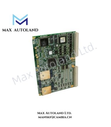
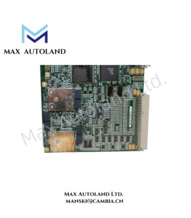
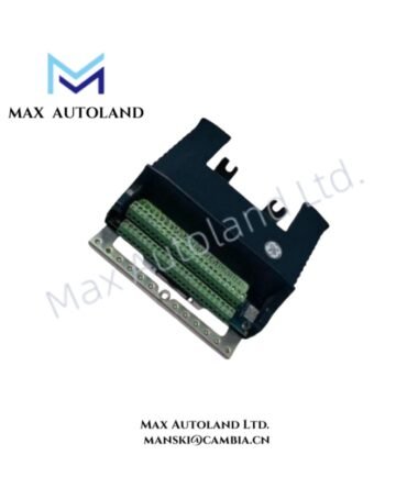
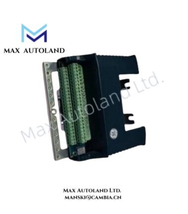
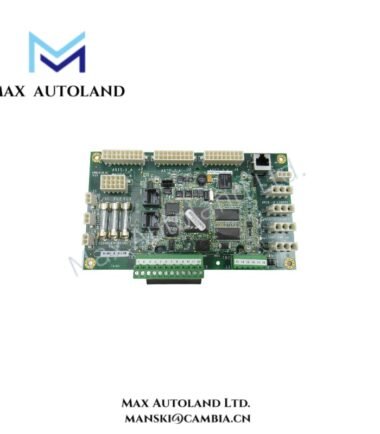
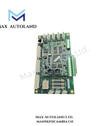
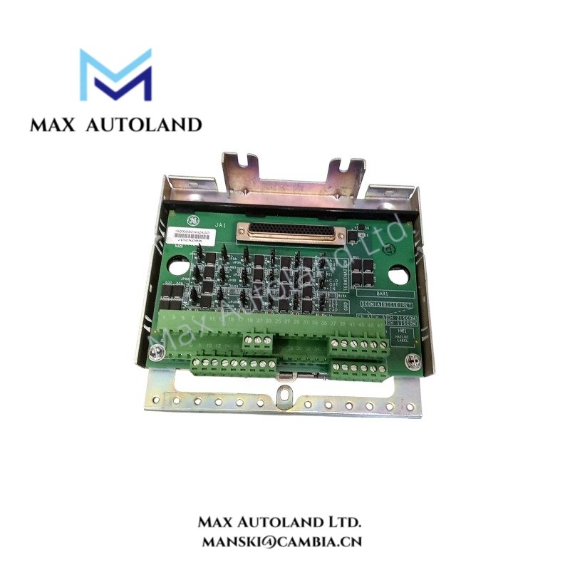
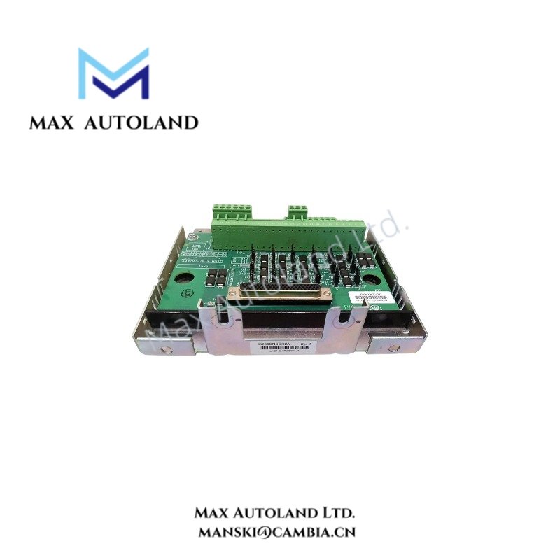
Configured for serial signal interfacing in the Mark VI control system, the General Electric IS200SSCAH2AGD (IS200SSCAH2 Serial Communication I/O Terminal Board) provides direct physical and electrical execution for multi-channel serial communication. The board supports up to six communication channels, with each channel configured for RS-232C, RS-485, or RS-422 signal transmission. A compatible PSCA I/O Pack connects to the controller through Ethernet and interfaces with the board through a DC-37 pin connector.
Hardware Specifications
| Parameter | Specification |
|---|---|
| Model | IS200SSCAH2AGD |
| Base Model | IS200SSCAH2 |
| Brand | General Electric |
| Manufacturer | General Electric |
| Series | Mark VI |
| Product Type | Serial Communication I/O Terminal Board |
| Origin | United States (USA) |
| Communication Channels | Up to 6 |
| Supported Serial Standards | RS-232C, RS-485, RS-422 |
| Channel Connection Points | 6 per channel |
| Signal Connections | Four signal lines A-D, signal return, shield common |
| I/O Pack Interface | DC-37 pin connector |
| Controller Communication | Ethernet through compatible PSCA I/O Pack |
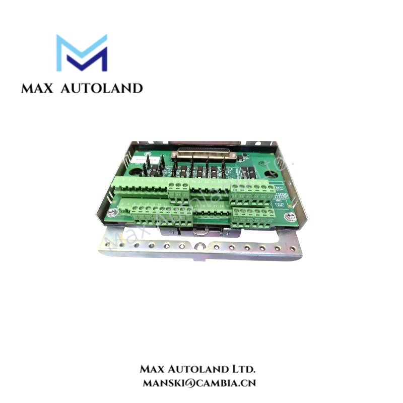
| Terminal Header | 48-terminal right-angle header |
| Terminal Block Support | Commercially available pluggable terminal blocks |
| Recommended Field Wiring | #18 AWG shielded twisted pair |
| Shield Ground Terminals | SCOM terminals 37-48 |
| Chassis Ground Mounting Holes | E1 and E2 |
| Mounting Method | DIN rail or direct cabinet mounting |
| Mounting Hardware | Sheet metal carrier and plastic insulator mount |
Mark VI I/O Communication and Interface Characteristics
The IS200SSCAH2AGD forms the physical termination layer between field serial circuits and the compatible PSCA I/O Pack. Each communication channel provides four signal lines identified as A-D, together with a signal return and shield common connection.
The compatible I/O Pack transfers communication data to the Mark VI controller through Ethernet. Therefore, the terminal board separates field wiring and controller-side communication into defined physical interfaces.
As a General Electric Mark VI component, the board also supports structured I/O density scaling by providing up to six serial communication channels on one terminal assembly. Each channel can use the required RS-232C, RS-485, or RS-422 electrical signaling standard according to the connected field device and system configuration.
Frequently Asked Questions
Q: How many serial communication channels does the IS200SSCAH2AGD support?
A: The terminal board supports up to six serial communication channels. Each channel provides four signal lines, a signal return, and a shield common connection.
Q: Which serial communication standards can each channel use?
A: Each channel can be configured for RS-232C, RS-485, or RS-422 communication signals.
Q: How should cable shielding be grounded on the board?
A: The cable shield ground must connect to one of the SCOM terminals numbered 37 through 48. The E1 and E2 mounting holes provide chassis ground connection points.
Field Installation Guidelines
Mount the IS200SSCAH2AGD using the specified sheet metal carrier and plastic insulator assembly on a DIN rail. Alternatively, install the assembly directly into the control cabinet when the mechanical arrangement requires cabinet mounting.
Use the 48-terminal right-angle header with compatible pluggable terminal blocks. Route serial communication wiring using shielded twisted-pair cable, typically #18 AWG as specified for the SSCA installation.
Separate serial signal wiring from high-current and high-noise conductors where practical. Maintain shield continuity through the cable route and terminate the shield according to the system grounding arrangement.
Connect chassis ground through the E1 or E2 mounting holes as required by the installation design. Connect the I/O cable shield ground to one of the designated SCOM terminals 37-48.
Verify the required RS-232C, RS-485, or RS-422 channel configuration before connecting field devices. Confirm the DC-37 pin connection between the terminal board and the compatible PSCA I/O Pack, then verify Ethernet communication between the I/O Pack and the Mark VI controller.