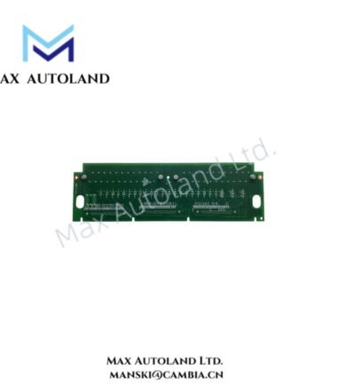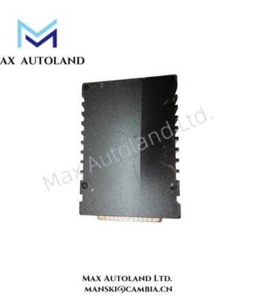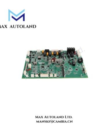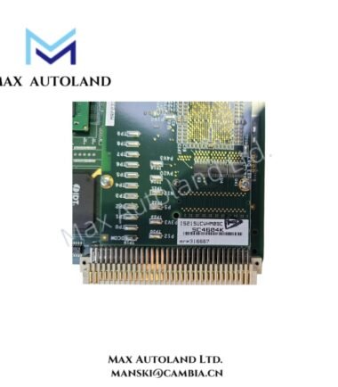

Overview
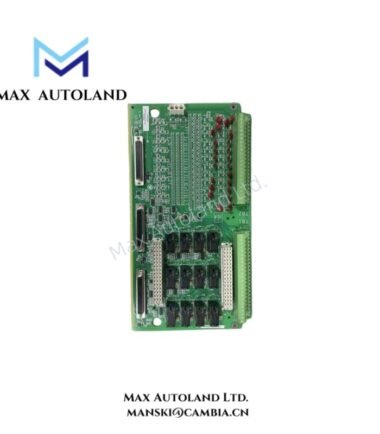
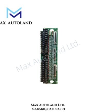
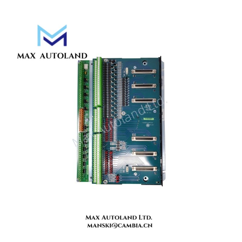
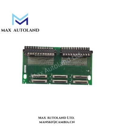
The General Electric IS400TCATH1A, also cataloged as the IS400TCAT Core Analog Terminal Board Assembly, provides analog signal conditioning and distribution interfaces within the Mark VIe control system. It routes field input signals to one or more PCAA modules and supports 4-20 mA transmitters, seismic signals, LVDT windings, and magnetic pulse rate flow signals. The board also provides hardware-voted analog outputs and current-limited 24 VDC outputs.
Hardware Specifications
| Parameter | Specification |
|---|---|
| Model | IS400TCATH1A |
| Brand | General Electric (GE) |
| Series | Mark VIe |
| Product Type | Core Analog Terminal Board Assembly |
| Board Designation | TCAT |
| Origin | United States (USA) |
| Analog Transmitter Inputs | 24 channels, 4-20 mA |
| Seismic Inputs | 12 signals |
| LVDT Inputs | 12 windings |
| Magnetic Pulse Rate Inputs | 2 signals |
| Analog Outputs | 3 hardware-voted 4-20 mA outputs |
| 24 VDC Outputs | 12 outputs, maximum 25 mA per output |
| Additional 24 VDC Outputs | 12 through the JGPA combination, maximum 25 mA per output |
| Power Supply Inputs | 15 VDC and 28 VDC supplies from one or more PCAA modules |
| Pulse Rate Measurement | Minimum input amplitude: 33 mV peak at 2 Hz; 827 mV peak at 12 kHz |
| Transmitter Return Configuration | Jumper-selectable grounded or floating return |
| Default Return Configuration | Floating (open jumper position) |
| Power Redundancy | Diode-OR arrangement for 15 VDC supplies |
| Overcurrent Protection | An affected 24 VDC output shuts down during an overcurrent condition |
| Physical Interface | Terminal blocks and jumper pins |
Mark VIe Analog Signal Distribution and Power Management
The TCAT terminal board distributes field input signals to connected PCAA modules. In redundant configurations, passive circuits support signal distribution across the connected processing modules.
The 4-20 mA transmitter inputs use jumper-selectable return configurations. Each input jumper determines whether the return terminal is grounded or floating. The documented default position is floating, with the jumper open.
The TCAT and JGPA combination provides up to 24 individual 24 VDC terminals for transmitter inputs. Each documented 24 VDC output has a maximum current rating of 25 mA. If an output experiences an overcurrent condition, the affected output shuts down. Once the overload is removed, the output returns to 24 VDC operation.
The board receives 15 VDC and 28 VDC supplies through the cabling connecting the TCAT and PCAA modules. The 15 VDC sources use diode-OR circuitry to support redundant power delivery. Internally, the 15 VDC supply biases the seismic inputs.
Magnetic pulse rate inputs have frequency-dependent minimum signal amplitudes. The specified minimum is 33 mV peak at 2 Hz and 827 mV peak at 12 kHz.
Frequently Asked Questions
Q: How many 4-20 mA analog outputs does the IS400TCATH1A provide?
A: The board provides three hardware-voted 4-20 mA analog outputs.
Q: How does the board handle an overcurrent condition on a 24 VDC output?
A: The affected output shuts down during an overcurrent condition. After the overload is removed, the output returns to 24 VDC operation.
Q: How are the 4-20 mA transmitter returns configured?
A: A jumper beside each input terminal selects a grounded or floating return. The documented default setting is floating, with the jumper open.
Field Installation Guidelines
- Verify the complete part number and board revision against the equipment documentation before installation.
- Isolate the applicable power sources and follow site lockout procedures before connecting or removing wiring.
- Confirm that the TCAT-to-PCAA cabling matches the specified 15 VDC and 28 VDC supply connections.
- Check each transmitter input jumper against the required grounded or floating return configuration.
- Separate low-level analog signal wiring from high-current switching and power conductors where practical.
- Apply the grounding and cable-shield termination methods specified in the Mark VIe installation documentation.
- Inspect terminal blocks, connectors, and jumper pins for damage or loose connections before energizing the board.
- Verify field wiring polarity, transmitter compatibility, and output current limits before commissioning.
- For pulse rate signals, confirm that the input amplitude and frequency fall within the documented measurement conditions.
- Do not assume hot-swap support, environmental ratings, or mounting requirements without confirmation from the applicable GE documentation.