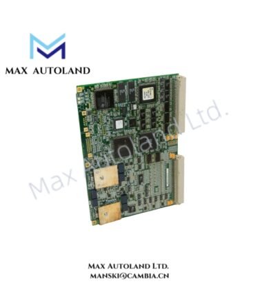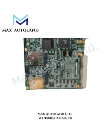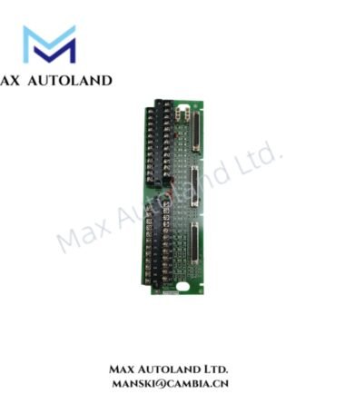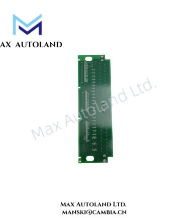

Overview
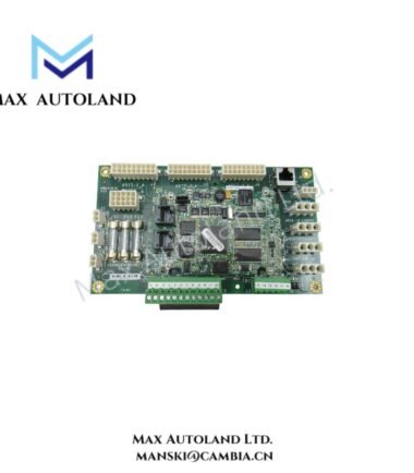
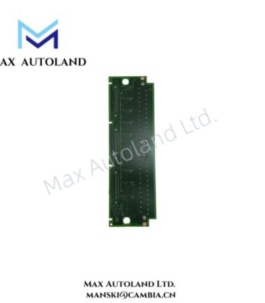
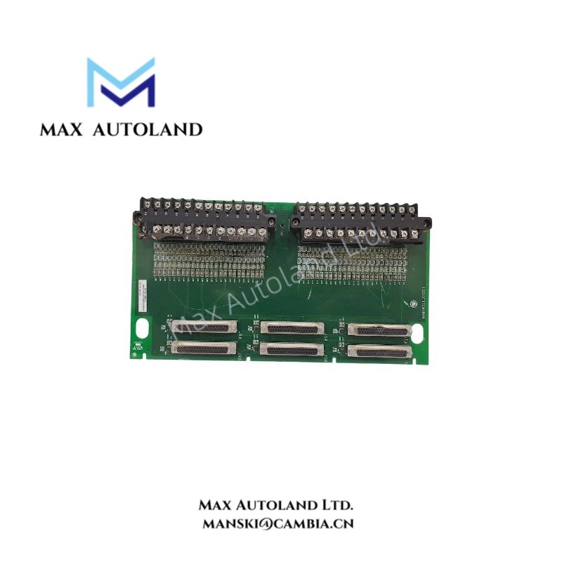
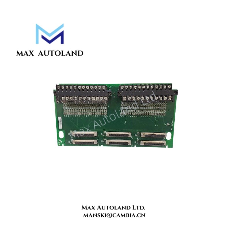
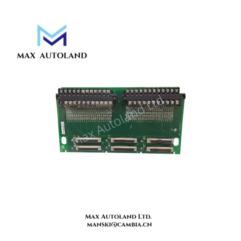
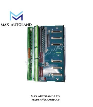
The GE IS200TBTCH1B, also cataloged as the IS200TBTC Thermocouple Input Terminal Board, provides thermocouple signal termination and distribution within the GE Mark VI turbine control system. It accepts 24 thermocouple inputs and routes signals to the associated I/O processors through DC-type connectors. The H1B variant supports triple modular redundancy (TMR) configurations through six connectors for connections to three VTCC processor boards.
Hardware Specifications
| Parameter | Specification |
|---|---|
| Model | IS200TBTCH1B |
| Brand | General Electric (GE) |
| Series | Mark VI |
| Product Type | Thermocouple Input Terminal Board |
| Input Channels | 24 |
| Supported Thermocouple Types | E, J, K, S, T |
| Input Span | -8 mV to +45 mV |
| Input Configuration | Grounded or ungrounded thermocouples |
| Maximum Cable Distance | 300 m (984 ft), as specified in the supplied data |
| Maximum Two-Way Cable Resistance | 450 ohms |
| Cold Junction Compensation | Two cold junction reference devices |
| Signal Processing | Analog-to-digital conversion and thermocouple linearization performed by the associated I/O processor |
| TMR Connections | Six DC-type connectors for three VTCC processor boards |
| Operating Temperature | 0 to +45 deg C |
| Dimensions | 15.9 cm high x 17.8 cm; third dimension not provided |
| Country of Origin | United States |
| Technical Manual | GEH-6421M |
Thermocouple Signal Processing and Cold Junction Compensation
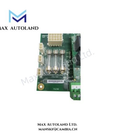
The IS200TBTCH1B terminates thermocouple wiring through two removable terminal blocks. Each block provides 24 terminals and accepts wires up to #12 AWG, according to the supplied installation information. The board incorporates high-frequency noise suppression and two cold junction reference devices.
The associated I/O processor performs analog-to-digital conversion and linearization according to the selected thermocouple type. Therefore, the terminal board provides the field wiring interface, while the processor performs the primary signal conversion and temperature calculation.
The H1B variant supports TMR signal distribution. Its six DC-type connectors provide the cable interfaces required to connect the terminal board to three VTCC processor boards in a Mark VI TMR configuration.
Frequently Asked Questions
Q: Which thermocouple types does the IS200TBTCH1B support?
A: The supplied Mark VI specifications list Type E, J, K, S, and T thermocouples. Additional Type B and N inputs are described for specific Mark VIe configurations using a compatible PTCC interface; compatibility should be verified against the applicable hardware documentation.
Q: How does the IS200TBTCH1B connect to the control processors?
A: In a Mark VI TMR configuration, the board uses six DC-type connectors and cables to connect to three VTCC processor boards. Confirm the connector assignments and cable part numbers against the system wiring documentation.
Q: Does the terminal board perform thermocouple linearization?
A: No. The associated I/O processor performs analog-to-digital conversion and thermocouple linearization. The terminal board provides field termination, signal routing, noise suppression, and cold junction reference devices.
Field Installation Guidelines
- Verify hardware compatibility. Confirm the IS200TBTCH1B part number, board revision, Mark VI rack configuration, and associated VTCC processors before installation.
- Connect field wiring. Terminate the thermocouple conductors at the designated removable terminal blocks. Follow the wiring diagram for terminal assignments and thermocouple polarity.
- Manage cable shielding. Route thermocouple cables away from high-current conductors and switching noise sources. Ground cable shields according to the GE installation manual and the plant grounding scheme.
- Check cable resistance and routing. Verify the field cable length and loop resistance against the documented limits. Avoid introducing additional resistance through loose terminals or unsuitable extension wiring.
- Verify connector configuration. For TMR installations, confirm all six DC-type cable connections and their assignments to the three VTCC processors. Do not assume simplex and TMR wiring arrangements are interchangeable.
- Inspect before energization. Check terminal tightness, conductor polarity, connector seating, grounding, and thermocouple type configuration. Follow the approved turbine control maintenance procedure before returning the system to service.
- Consult the technical manual. Use GEH-6421M and the applicable system drawings to verify terminal assignments, installation requirements, and processor compatibility. Do not infer unsupported hot-swap procedures or power requirements.