


Overview
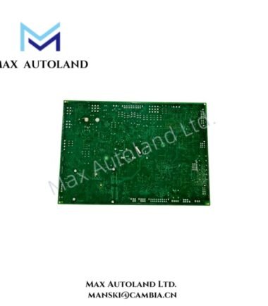
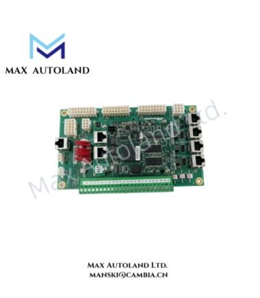
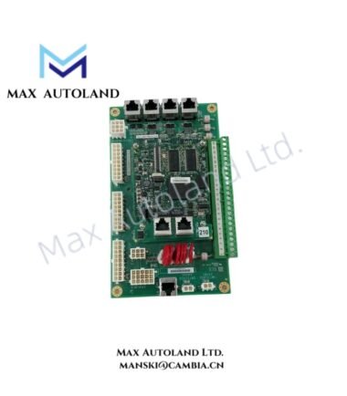
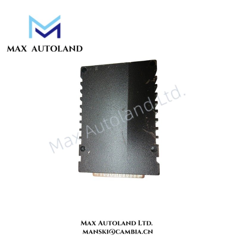
Configured for analog signal acquisition, conversion, and output within the GE Mark VIe control system, the GE IS220PAICH1BG (IS220PAICH1B PAIC Pack) provides direct electrical interfacing between field analog circuits and the control network. It accepts configurable voltage and current inputs, provides two 0-20 mA outputs, and communicates through dual 10/100 Ethernet ports.
Hardware Specifications
| Parameter | Specification |
|---|---|
| Model | IS220PAICH1BG |
| Base Model | IS220PAICH1B |
| Brand | General Electric (GE) |
| Product Series | Mark VIe |
| Module Type | PAIC Analog Input/Output Pack |
| Analog Inputs | Up to 10 analog inputs |
| Inputs 1-8 | Configurable for +/-5 V, +/-10 V, or 0-20 mA |
| Inputs 9-10 | Configurable for +/-1 mA or 0-20 mA |
| Analog Outputs | 2 channels, 0-20 mA |
| Ethernet Communication | 2 independent 10/100 Ethernet ports |
| Ethernet Connector | RJ45 |
| Network Function | Supports redundant network connections |
| Diagnostic Interface | Local infrared serial communication port |
| Status Indication | Visual status LEDs |
| Power Interface | 3-pin power input connector |
| Power Circuit | Soft-start and inrush current limiting |
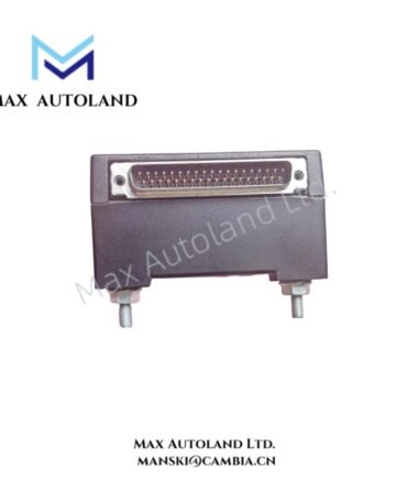
| Compatible Terminal Boards | TBAIH1C and STAI |
| Processor | On-board high-speed processor |
| Memory | RAM and Flash memory |
| Hardware Watchdog | Integrated |
| Reset Circuit | Integrated |
| Temperature Monitoring | Internal temperature sensor |
| Hardware Identification | Electronic ID packet for hardware and firmware identification |
GE Mark VIe Analog Signal Interface
The PAIC pack processes both voltage and current field signals. Inputs 1 through 8 accept +/-5 V, +/-10 V, or 0-20 mA configurations, while inputs 9 and 10 accept +/-1 mA or 0-20 mA signals. Therefore, the input configuration must match the connected field device and terminal-board wiring.
The module also provides two independent 0-20 mA analog outputs. These outputs support current-loop transmission from the Mark VIe control architecture to connected field circuits.
For network communication, the pack provides two independent 10/100 Ethernet interfaces through RJ45 connectors. The dual interfaces support network redundancy requirements within the Mark VIe architecture. In addition, the local infrared serial interface provides a direct diagnostic communication path.
The hardware includes a watchdog timer, reset circuit, internal temperature sensor, and electronic identification data. Consequently, the control system can monitor hardware status and identify the installed hardware and firmware configuration.
Frequently Asked Questions
Q: How many analog input channels does the IS220PAICH1BG provide?
A: The PAIC pack provides up to 10 analog inputs. Inputs 1-8 support +/-5 V, +/-10 V, and 0-20 mA configurations, while inputs 9-10 support +/-1 mA and 0-20 mA.
Q: What analog output signal does the IS220PAICH1BG provide?
A: The module provides two analog output channels using 0-20 mA current-loop signals.
Q: What communication interfaces are available on the IS220PAICH1BG?
A: The pack provides two independent 10/100 Ethernet ports with RJ45 connectors. It also includes a local infrared serial communication port for diagnostics.
Field Installation Guidelines
- Verify the complete IS220PAICH1BG model designation before installation.
- Confirm terminal-board compatibility with the installed TBAIH1C or STAI interface.
- Match each analog input configuration to the connected field signal before energizing the circuit.
- Route analog signal wiring separately from high-voltage and high-current power conductors where practical.
- Use appropriate shielded instrumentation cable for low-level analog signals.
- Terminate cable shields according to the site’s grounding and EMC practices.
- Check polarity and signal-loop wiring before applying power.
- Inspect the 3-pin power connector and verify secure mechanical engagement.
- Connect Ethernet cabling only after confirming the intended network topology and redundancy arrangement.
- Check status LEDs after startup and review diagnostic information if the pack reports a fault.
- Maintain adequate separation between signal, power, and communication wiring to reduce electrical interference.
- Do not apply field signals outside the specified input ranges.