Overview
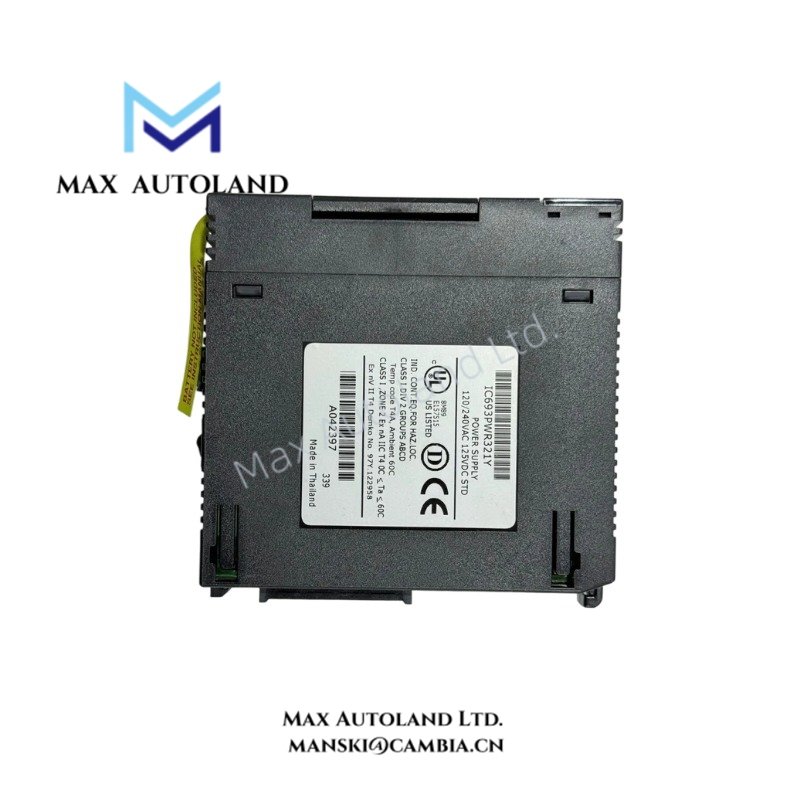
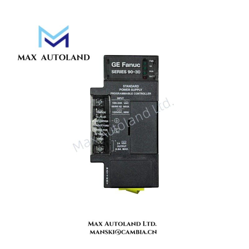
Configured for AC/DC power conversion and regulated DC distribution in Series 90-30 PLC hardware, the GE IC693PWR321 (IC693PWR321 Power Supply Module) provides electrical power for connected control components. It accepts 120/240 VAC or 125 VDC input and provides 5 VDC and 24 VDC output power.
Hardware Specifications
| Parameter | Specification |
|---|---|
| Model | IC693PWR321 |
| Brand | General Electric |
| Series | Series 90-30 |
| Product Type | Standard Power Supply Module |
| Lifecycle Status | Discontinued/Obsolete |
| Origin | USA |
| Weight | 0.55 kg |
| Dimensions | Estimated shipping size: 6.8 x 13 x 13.5 cm |
| Nominal Rated Voltage | 120/240 VAC or 125 VDC |
| Input Power | 90 VA with VAC input; 50 W with VDC input |
| Inrush Current | 4 A peak, 250 milliseconds maximum |
| Output Voltage | 5 VDC; 24 VDC relay; 24 VDC isolated |
| 5 VDC Output Power | 15 W maximum |
| 24 VDC Relay Output Power | 15 W maximum |
| 24 VDC Isolated Output Power | 20 W maximum |
| Hold-up Time | 20 milliseconds minimum |
| Communication Interface | RS-485 communication port |
PLC Power and Communication Interface
The IC693PWR321 receives either 120/240 VAC or 125 VDC at its input terminals. It converts the applied input power into regulated DC output circuits for Series 90-30 control hardware. The supplied output ratings identify separate 5 VDC, 24 VDC relay, and 24 VDC isolated power capacities.
In addition, the module specification identifies an RS-485 communication port. Therefore, installation should maintain appropriate electrical separation between communication wiring and power conductors. Route RS-485 wiring away from high-current switching paths where practical to reduce electrical interference.
The specified 4 A peak inrush current lasts for a maximum of 250 milliseconds. Consequently, upstream protection and source capacity should account for the initial energization current.
Frequently Asked Questions
Q: What input voltages does the IC693PWR321 accept?
A: The module accepts 120/240 VAC or 125 VDC input.
Q: What output circuits does the IC693PWR321 provide?
A: The supplied specifications identify 5 VDC output rated at 15 W maximum, 24 VDC relay output rated at 15 W maximum, and 24 VDC isolated output rated at 20 W maximum.
Q: What is the specified hold-up time?
A: The minimum specified hold-up time is 20 milliseconds.
Field Installation Guidelines
Install the IC693PWR321 in the designated Series 90-30 power supply position and secure the module according to the rack or backplane installation procedure.
Before wiring, isolate the incoming power source and verify the input voltage type. Use wiring and upstream protection suitable for the selected AC or DC input.
Keep power conductors physically separated from RS-485 communication wiring where possible. Avoid routing communication cables parallel to high-current switching conductors for extended distances.
Terminate protective and functional grounding connections according to the installation requirements of the complete Series 90-30 system. Maintain secure terminal connections and inspect conductors for mechanical damage before energizing the system.
Because the module has a specified 4 A peak inrush current, verify that the upstream power source and protection devices can accommodate the stated energization condition.
Do not exceed the specified output power ratings for the individual DC output circuits. Also, confirm the required load distribution before applying power to the installed system.