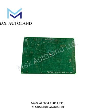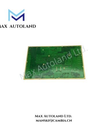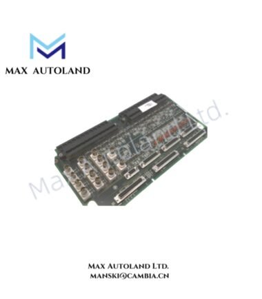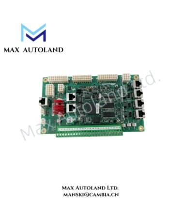



Overview
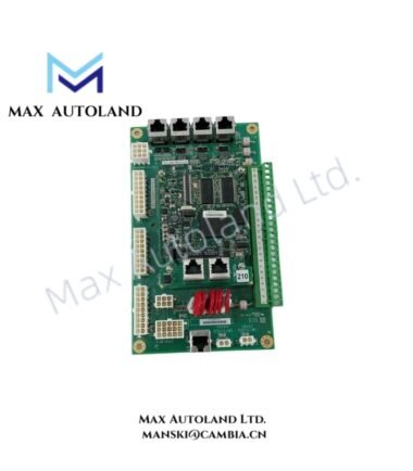
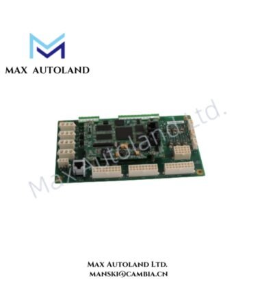
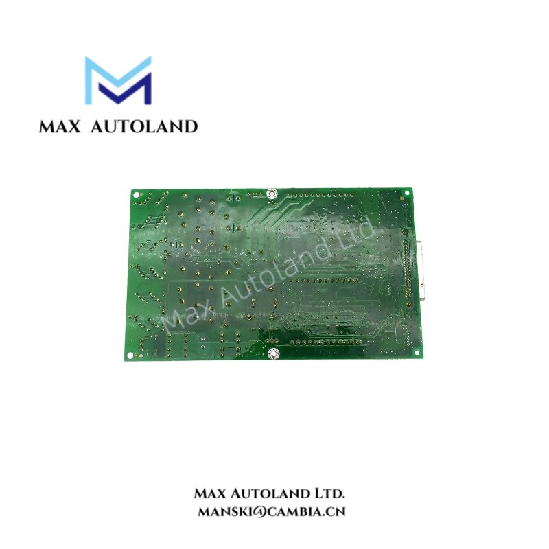
Configured for thermocouple terminal connections in the General Electric Mark VI control system, the General Electric IS200STTCH2A (IS200STTCH2A DIN Rail Thermocouple Terminal Board) provides direct physical termination through a 48-position terminal strip and a 37-position female DC connector.
Hardware Specifications
| Parameter | Specification |
|---|---|
| Model | IS200STTCH2A |
| Brand | General Electric |
| Series | Mark VI |
| Function | Terminal Board |
| Product Type | DIN Rail Mounted Thermocouple Terminal Board |
| Origin | Not specified in supplied data |
| Weight | 1.14 kg |
| Dimensions | 22.5 cm x 16.7 cm x 5.5 cm |
| Terminal Strip | 48-position, divided into two 24-position sections |
| Terminal Connection | Screw connections |
| Cable Connector | 37-position female DC connector |
| Mounting | DIN rail |
| Integrated Circuit | 1, identified as U1 |
| Board Identification Codes | 6BA00, 94V-0 |
Industrial Control and Terminal Interface Characteristics
The IS200STTCH2A uses a DIN rail mounting arrangement for mechanical installation within a Mark VI control cabinet. Its 48-position terminal strip provides two groups of 24 screw connections for field wiring termination.
In addition, the board includes a 37-position female DC connector on the opposite side. This connector provides the board-side interface for the associated cable connection. The board contains rows of capacitors, resistors, and ferrite beads in the central area. These components support high-frequency noise suppression within the terminal interface circuitry.
Because the supplied data identifies the board as a thermocouple terminal board, field wiring should follow the applicable Mark VI thermocouple input wiring and grounding practices. Avoid routing thermocouple wiring alongside high-current or high-switching conductors where electrical noise could couple into low-level temperature signals.
Frequently Asked Questions
Q: How is the IS200STTCH2A mechanically mounted?
A: The IS200STTCH2A is designed for DIN rail mounting. The DIN rail provides the mechanical support for cabinet installation.
Q: How many field termination positions does the board provide?
A: The board has a 48-position terminal strip. It is divided into two sections, with 24 screw connections per section.
Q: What cable interface does the board provide?
A: The board has one 37-position female DC connector located on the opposite side of the 48-position terminal strip.
Field Installation Guidelines
- Mount the IS200STTCH2A securely on the specified DIN rail and verify that the mounting position provides adequate access to both terminal sections.
- Identify each field conductor before termination and match the wiring to the applicable Mark VI system documentation.
- Keep thermocouple signal wiring physically separated from high-current power wiring and switching conductors to reduce electromagnetic interference.
- Maintain proper shield and grounding practices according to the system wiring design. Do not create unintended ground loops through cable shields.
- Inspect all screw-terminal connections for correct conductor placement and secure mechanical termination before energizing the associated control circuit.
- Verify the 37-position cable connector orientation and seating before commissioning.
- Do not apply power or field signals to unverified terminals. Confirm terminal assignments against the applicable system drawings before startup.