Overview
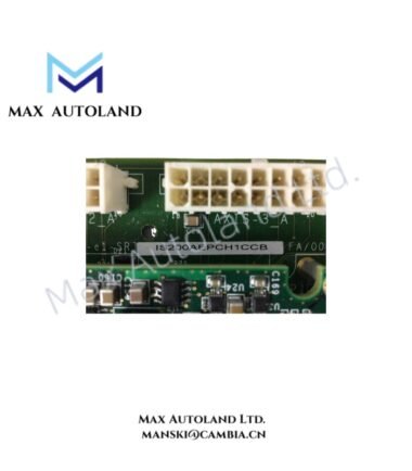
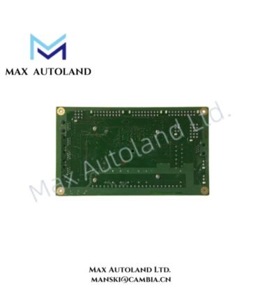
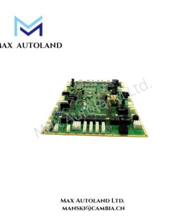
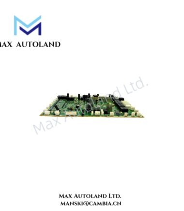
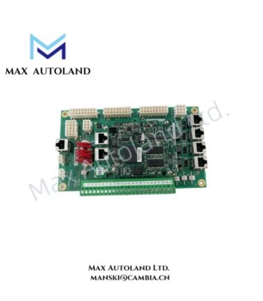
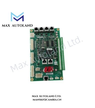
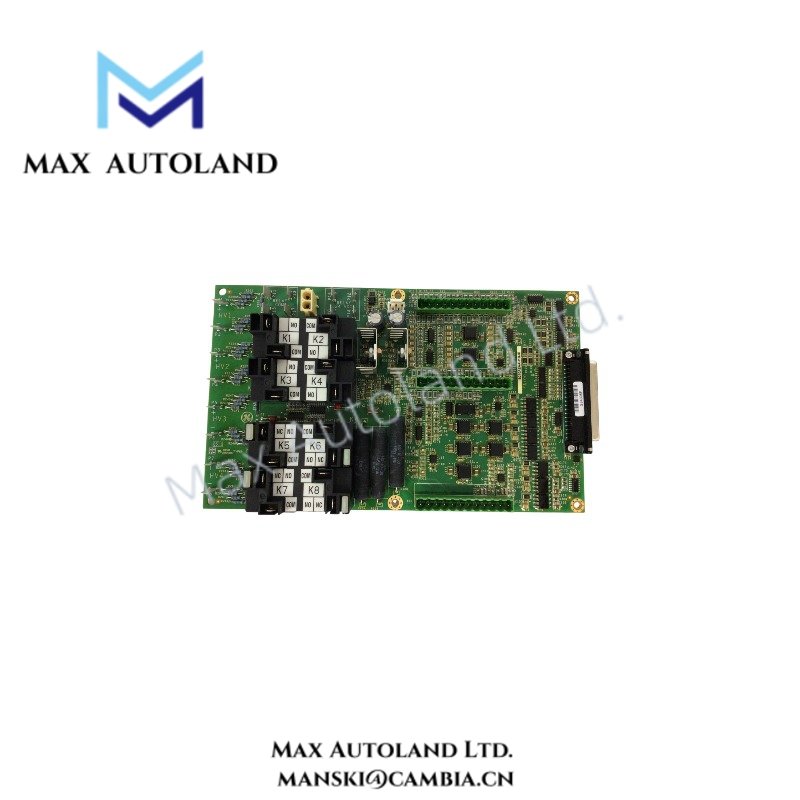
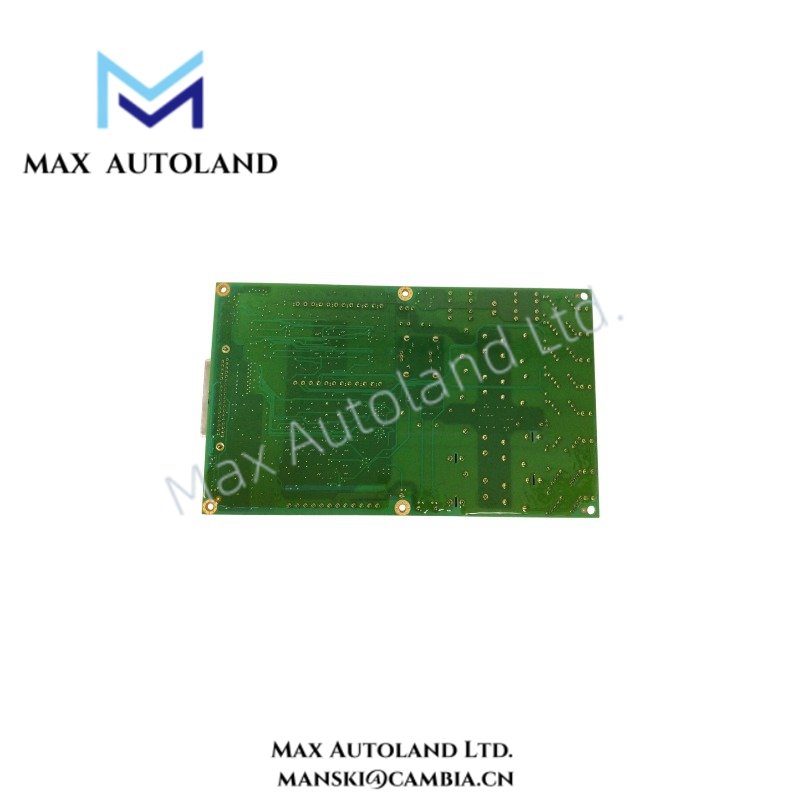
Configured for protection logic execution and hardware signal processing in GE Mark VI / Mark VIe platforms, the GE IS210BPPH2BLD (IS210BPPH2BLD Protection Processor Board) provides direct hardware-level processing for turbine control and protection functions. The board supports real-time monitoring and protection logic within the associated control architecture.
Hardware Specifications
| Parameter | Specification |
|---|---|
| Model | IS210BPPH2BLD |
| Brand | General Electric (GE) |
| Product Series | Mark VI / Mark VIe |
| Product Type | Protection Processor Board |
| Component Type | Printed Circuit Board (PCB) |
| Application | Turbine control and protection systems |
| Primary Function | Protection logic execution and hardware signal processing |
| Board Color | Green |
| Operating Environment | Industrial control environment |
| Signal Processing | Protection-related hardware signal processing |
| System Interface | Mark VI / Mark VIe control architecture |
GE Industrial Control and Backplane Processing
The IS210BPPH2BLD operates as a hardware processing element within the GE Mark VI / Mark VIe architecture. Therefore, installation should preserve the specified board position, connector engagement, and backplane interface.
The supplied data identifies protection logic execution and signal processing, but it does not specify a particular communication protocol, backplane transfer rate, or firmware revision. Consequently, those parameters should be verified against the applicable GE system documentation before replacement or commissioning.
Firmware compatibility also requires verification when replacing a board. In addition, technicians should confirm the system configuration, board revision, connector arrangement, and associated application software before energizing the assembly.
Frequently Asked Questions
Q: Does the supplied specification confirm a hot-swap capability for the IS210BPPH2BLD?
A: No. The supplied data does not define hot-swap operation. The board should therefore be removed or installed only under the procedures specified for the associated Mark VI / Mark VIe system.
Q: What operating temperature range is specified for the IS210BPPH2BLD?
A: No numerical operating temperature range is provided in the supplied information. The applicable GE hardware documentation should be consulted for environmental limits.
Q: Is a specific backplane communication speed specified?
A: No. The supplied information identifies the board as a Mark VI / Mark VIe protection processor board but does not provide a numerical backplane communication rate.
Field Installation Guidelines
- Isolate system power according to the applicable GE maintenance procedure before removing or installing the board.
- Verify the complete IS210BPPH2BLD model designation and board revision before installation.
- Inspect the PCB, connectors, and mating backplane interface for contamination, mechanical damage, or bent contacts.
- Maintain proper electrostatic discharge protection when handling the exposed circuit board.
- Insert the board in the designated rack position and ensure complete connector engagement.
- Route adjacent wiring so that it does not mechanically interfere with the board, connectors, or ventilation paths.
- Keep signal wiring separated from high-current switching conductors where the cabinet design permits.
- Apply the cabinet grounding and shield termination practices specified by the applicable GE control-system documentation.
- After installation, verify board recognition, system configuration, diagnostic status, and protection logic operation before returning the control system to service.