
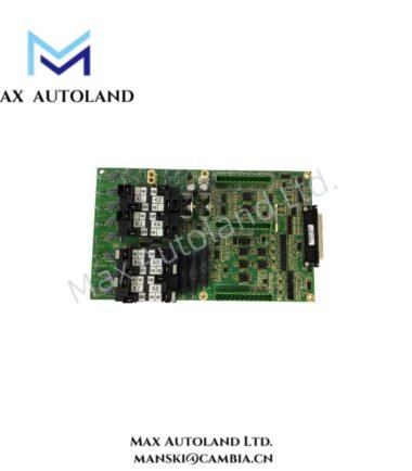

Overview
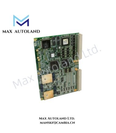
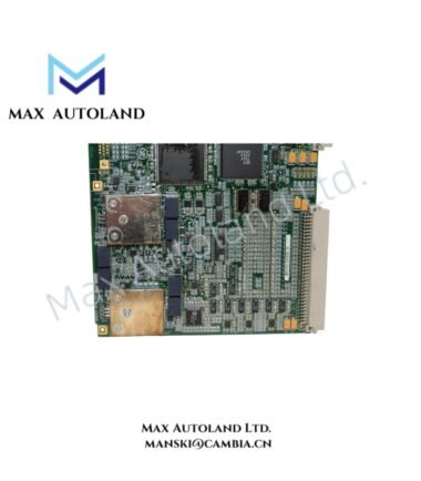
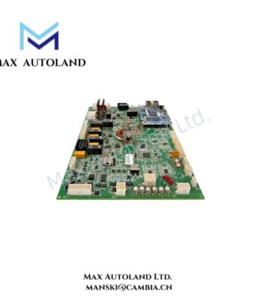
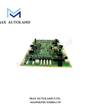
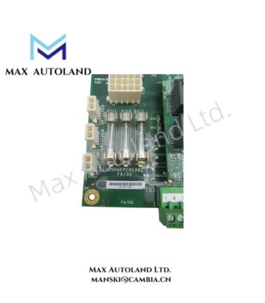
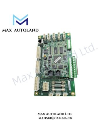
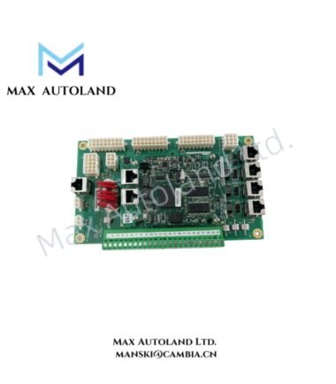
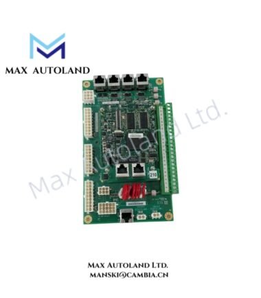
Configured for converter control processing and VME-based board-level computing, the GE IS210MACCH1AEF (IS210MACCH1A Converter Control Board) provides direct hardware processing through a 6U single-slot VME architecture. The supplied data identifies an Intel Ultra Low Voltage Celeron processor operating at either 400 MHz or 650 MHz.
Hardware Specifications
| Parameter | Specification |
|---|---|
| Model | IS210MACCH1AEF |
| Base Model | IS210MACCH1A |
| Brand | General Electric |
| Product Type | Converter Control Board |
| Board Architecture | 6U single-slot VME Single Board Computer (SBC) |
| Processor | Intel Ultra Low Voltage Celeron |
| Processor Speed | 400 MHz or 650 MHz |
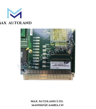
| VME Interface | 6U single-slot VME architecture |
| Dimensions | 2.1 cm x 18.8 cm x 26.2 cm |
| Weight | 0.65 kg |
| Estimated Shipping Size | 2.1 cm x 18.8 cm x 26.2 cm |
VME Computing and Converter Control Characteristics
The IS210MACCH1AEF uses a 6U single-slot VME form factor for board-level computing and system integration. Therefore, installation depends on a compatible VME backplane, slot geometry, and associated system hardware.
The supplied specification identifies an Intel Ultra Low Voltage Celeron processor with selectable operating speeds of 400 MHz or 650 MHz. However, the available data does not define memory capacity, VME bus transfer rate, storage interfaces, I/O channels, or firmware configuration.
Because the source information does not specify GE-specific Profinet, EtherNet/IP, or other network interfaces, those functions should not be assumed for this board. Instead, system engineers should verify the installed backplane and application-specific interface documentation before integration.
Frequently Asked Questions (FAQ)
Q: What processor does the IS210MACCH1AEF use?
A: The supplied specification identifies an Intel Ultra Low Voltage Celeron processor with a 400 MHz or 650 MHz operating speed.
Q: What mechanical form factor does the board use?
A: The board uses a 6U single-slot VME Single Board Computer format.
Q: What are the specified power consumption and operating temperature limits?
A: The supplied data does not specify either parameter. Engineers should obtain the applicable system-level or board-level documentation before defining environmental or power requirements.
Field Installation Guidelines
- Confirm that the target chassis provides a compatible 6U VME slot and backplane interface.
- Isolate system power before inserting or removing the board unless the equipment documentation explicitly permits hot insertion.
- Align the board with the VME card guides before applying insertion force.
- Secure the front-panel hardware after the board reaches its fully seated position.
- Inspect the backplane connector for contamination, bent contacts, or mechanical damage before installation.
- Keep processor and backplane wiring separated from high-current switching conductors where practical.
- Connect cable shields according to the cabinet grounding design and the applicable GE system documentation.
- Verify board seating, backplane connections, and processor configuration before applying system power.
- Do not assume hot-swap capability, operating temperature limits, or power consumption values without supporting technical documentation.
- After installation, verify processor operation and system-level VME communication through the applicable diagnostic procedure.