Overview
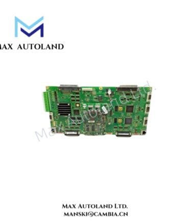
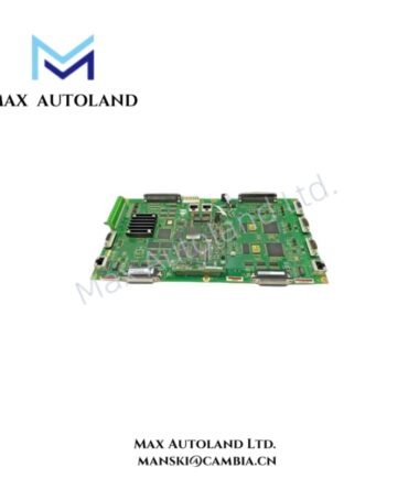
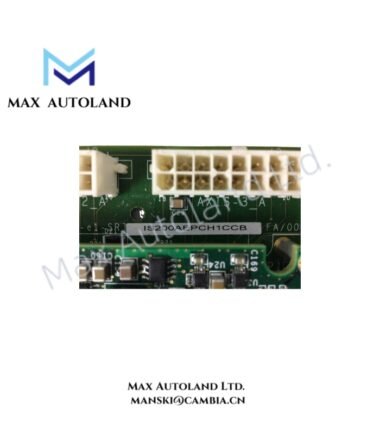
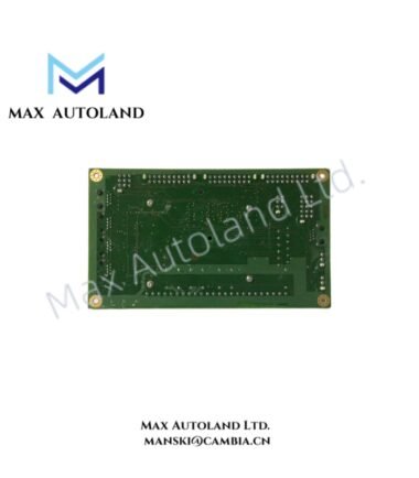
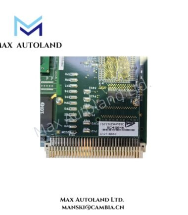
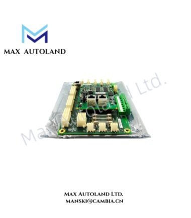
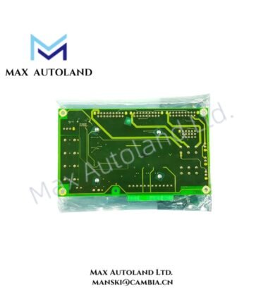
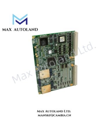
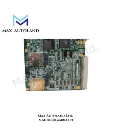
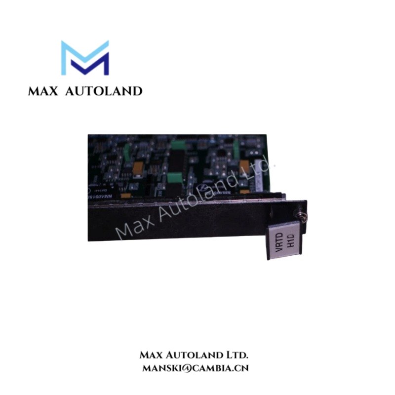
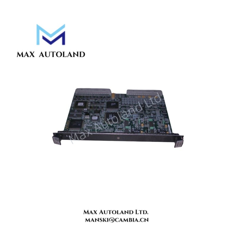
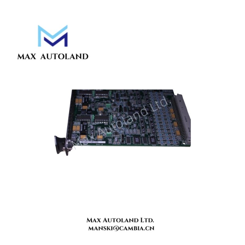
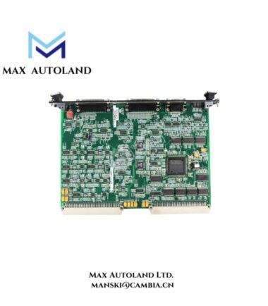
Configured for multi-channel RTD signal acquisition in the Speedtronic Mark VI control system, the GE IS200VRTDH1DAA (IS200VRTDH1DAA VME Resistance Temperature Detector Card) converts RTD resistance inputs into digital temperature data for control and monitoring.
Hardware Specifications
| Parameter | Specification |
|---|---|
| Model | IS200VRTDH1DAA |
| Brand | General Electric (GE) |
| Series | Mark VI Speedtronic Control System |
| Board Type | VME Resistance Temperature Detector (VRTD) Processor Board |
| Sensor Inputs | Up to 16 channels of 3-wire RTDs |
| Supported RTD Types | Platinum, copper, and nickel RTDs |
| Example RTD Ratings | 10 ohm, 100 ohm, 200 ohm platinum RTDs |
| A/D Conversion | 14-bit resolution |
| Excitation | Multiplexed DC excitation current |
| System Architecture | Simplex and TMR |
| Fault Detection | Open-circuit, short-circuit, and out-of-range checking |
| Status Indication | Power, Run, and Fault/Alert LEDs |
| Mounting | VME rack-mounted |
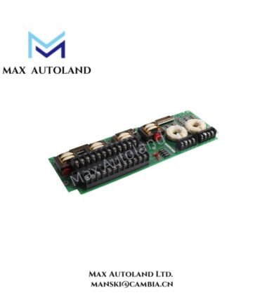
| Terminal Interface | Molded cable connection to companion terminal boards such as TRTD |
| Conformal Coating | Yes |
Mark VI RTD Signal Acquisition and I/O Scaling
The IS200VRTDH1DAA accepts resistance signals from connected RTDs and applies multiplexed DC excitation to the selected sensor channel. The board then converts the resulting analog signal through a 14-bit A/D converter.
The VRTD architecture supports multiple RTD channels while coordinating signal multiplexing within Simplex and TMR Mark VI configurations. In TMR installations, the control architecture coordinates the corresponding signal paths across the R, S, and T racks to avoid conflicting channel assignments.
The board also performs hardware and software limit checking. Therefore, the control system can identify open-circuit, short-circuit, and out-of-range RTD conditions. Front-panel LEDs provide local indications for power, run, and fault or alert states.
Frequently Asked Questions (FAQ)
Q: How many RTD inputs can the IS200VRTDH1DAA accommodate?
A: The supplied specification identifies support for up to 16 channels of 3-wire RTDs.
Q: What type of analog-to-digital conversion does the board use?
A: The board uses a 14-bit A/D converter to digitize the RTD measurement signals.
Q: Can the IS200VRTDH1DAA operate in a TMR Mark VI configuration?
A: Yes. The supplied data identifies compatibility with both Simplex and Triple Modular Redundant configurations, with signal multiplexing coordinated across the R, S, and T racks.
Field Installation Guidelines
Install the IS200VRTDH1DAA in the designated VME rack position and verify the board orientation before connecting the molded cable interface.
Connect each RTD channel according to the applicable Mark VI terminal-board wiring arrangement. Maintain the designated three-wire RTD connections because incorrect lead assignment can introduce measurement errors.
Route RTD wiring separately from high-current and switching conductors where the cabinet design permits. Avoid unnecessary parallel routing with power cables to reduce electrical interference.
Connect the companion terminal board, such as the TRTD, using the specified molded cable assembly. Verify connector seating before applying system power.
For shielded RTD wiring, terminate shields according to the Mark VI grounding scheme. Do not create unintended shield-to-ground paths at multiple termination points.
Before commissioning, verify channel identification, RTD wiring continuity, sensor type, and terminal-board connections. Then confirm the board status LEDs and verify that the Mark VI system receives valid temperature values without open-circuit, short-circuit, or out-of-range indications.