
Overview
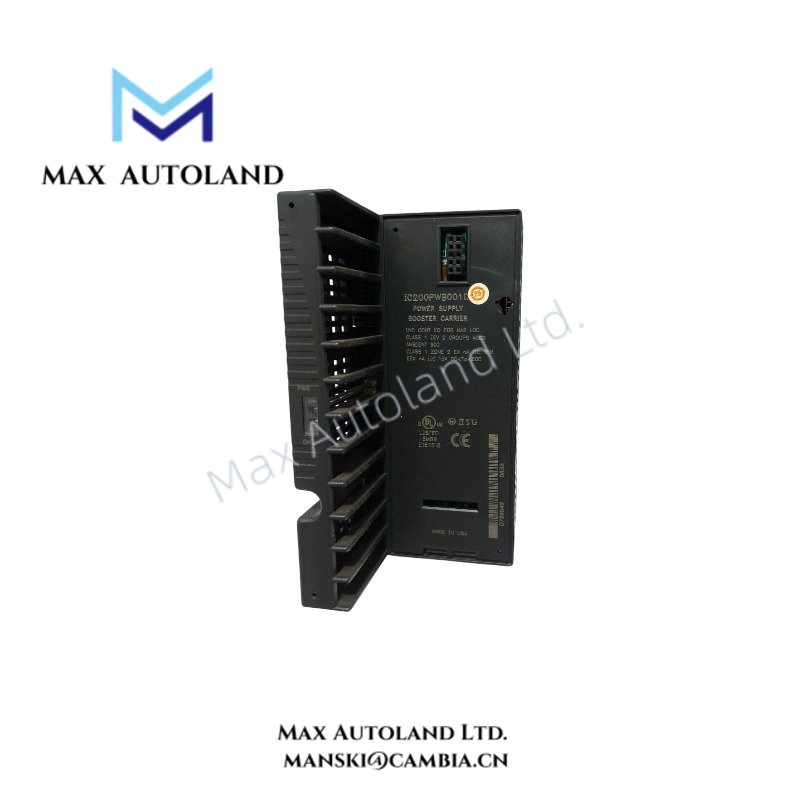
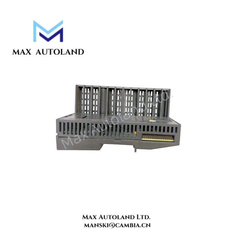
Configured for extending power distribution in VersaMax I/O assemblies, the General Electric IC200PWB001D (IC200PWB001 Power Supply Booster Carrier) provides direct electrical support for an additional power supply and the I/O modules positioned to its right. The carrier distributes booster supply power through the VersaMax assembly and separates the powered section from the preceding power budget.
Suffix Breakdown & Model Matrix
The supplied documentation identifies IC200PWB001D as the full product model and IC200PWB001 as the spare or base model. No further suffix breakdown is specified in the available technical data.
Hardware Specifications
| Parameter | Specification |
|---|---|
| Model | IC200PWB001D |
| Spare Model | IC200PWB001 |
| Brand | General Electric |
| Series | VersaMax |
| Product Type | Power Supply Booster Carrier |
| Weight | 0.12 kg |
| Dimensions | 13 x 7.2 x 6.8 cm estimated shipping size |
| Operating Temp | -20 to 70 deg C |
| Storage Temp | -40 to 85 deg C |
| Input Voltage | 24 VDC |
| Power Consumption | 2.5 W power dissipation |
| Isolation Rating | 1500 VAC |
| Enclosure Rating | IP20 |
| Mounting | DIN rail or panel mounting |
| DIN Rail Size | 7.5 mm x 35 mm |
| Status Indicators | PWR LED, OK LED |
| Core Function | Hosts an additional power supply and distributes power to I/O modules |
VersaMax I/O Density Scaling
The IC200PWB001D supports I/O density scaling by creating an additional power distribution section within a General Electric VersaMax assembly. The booster carrier hosts an additional power supply and distributes its output to compatible I/O modules located to the right.
This arrangement allows the physical I/O assembly to extend beyond the power capacity of a single supply section. However, the installation must follow the VersaMax module arrangement and power budgeting requirements. The booster carrier does not replace the CPU or NIU communication function.
Frequently Asked Questions
Q: Does the IC200PWB001D distribute power to the entire VersaMax assembly?
A: No. The carrier supports an additional power supply section and distributes power to I/O modules positioned to its right, extending until the next booster carrier or CPU/NIU boundary as defined by the system configuration.
Q: Can the IC200PWB001D be installed on a DIN rail?
A: Yes. The supplied specifications identify DIN rail mounting using a 7.5 mm x 35 mm rail. Panel mounting is also available where additional mechanical resistance to vibration or shock is required.
Q: Does the booster carrier provide CPU or network communication?
A: The supplied product information defines the IC200PWB001D as a power supply booster carrier. Its primary function is power distribution rather than CPU processing or network communication.
Field Installation Guidelines
Mount the IC200PWB001D on a compatible DIN rail or secure it by panel mounting where the installation environment requires increased mechanical stability.
Install the carrier according to the physical VersaMax module sequence. Verify the position of the additional power supply and the I/O modules that receive power from the booster section before energizing the assembly.
Use appropriately rated 24 VDC wiring and separate power wiring from high-noise conductors where practical. Maintain correct grounding practices for the control cabinet and connected power supply.
Before startup, verify supply polarity, module seating, mechanical retention, and the applicable power load for each I/O section. Check the PWR and OK indicators after energizing the assembly.