Overview
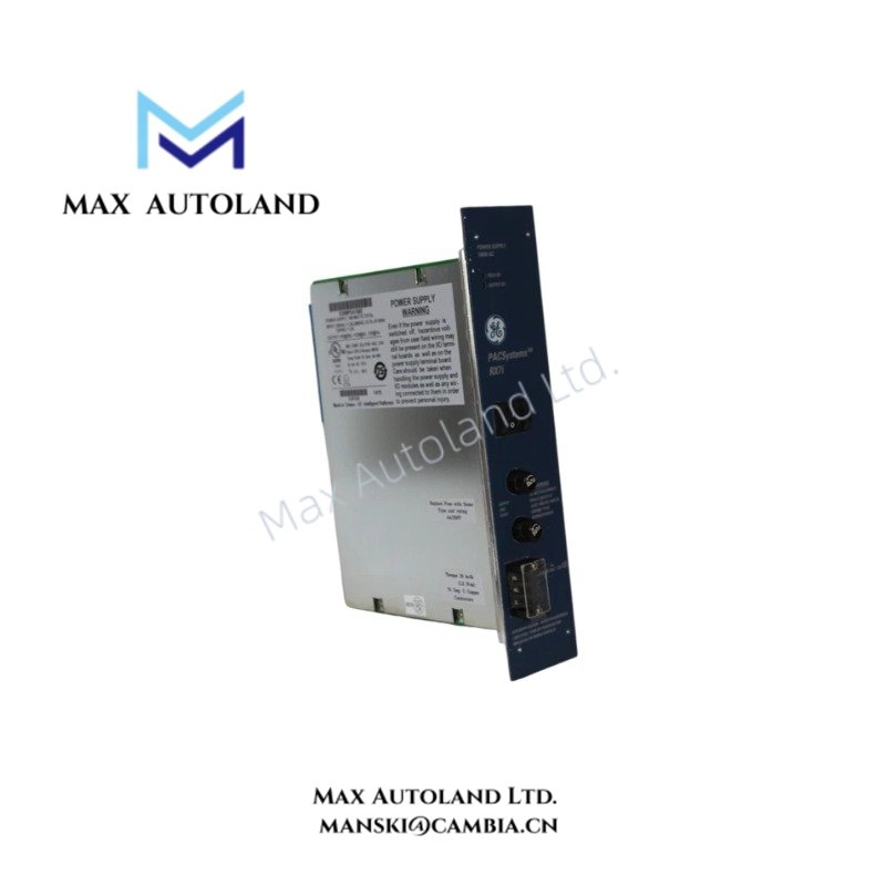
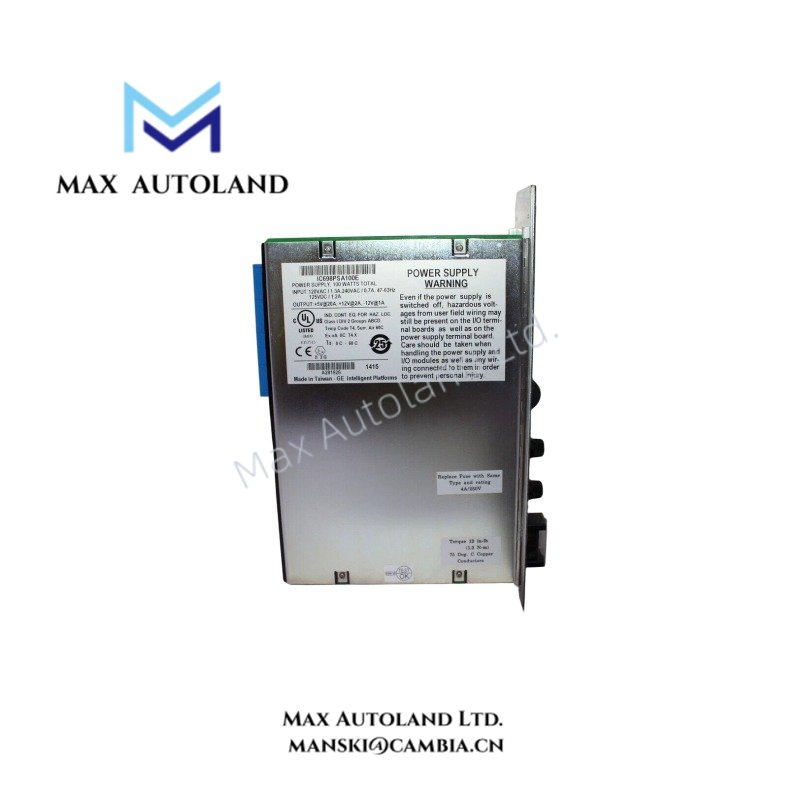
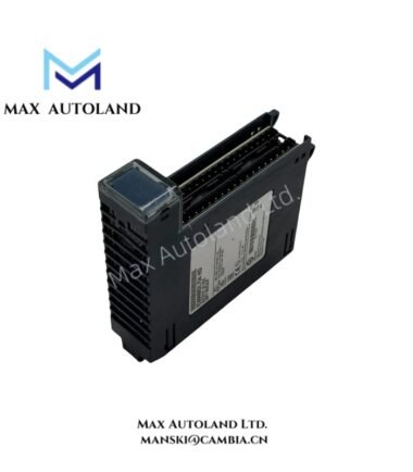
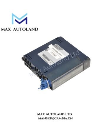
Configured to provide regulated DC power to RX7i backplane loads, the GE Fanuc Emerson IC698PSA100 (IC698PSA100 power supply module) accepts AC or DC input and distributes power through 5 VDC, 12 VDC, and -12 VDC outputs. The module mounts in the leftmost slot of an RX7i universal backplane.
Hardware Specifications
| Parameter | Specification |
|---|---|
| Model | IC698PSA100 |
| Brand | GE Fanuc Emerson |
| Product Line | PACSystem RX7i |
| Product Type | Power Supply Module |
| Weight | 5.06 lb (2.30 kg) |
| Mounting Position | Leftmost slot |
| Input Voltage Range | 85 to 264 VAC; 100-150 VDC |
| AC Input Frequency | 47-63 Hz |
| Maximum Typical Input Power | 125 W |
| Maximum Input Power | 150 W |
| Maximum Output Power | 100 W total |
| Output Voltages | 5 VDC, 12 VDC, -12 VDC |
| Output Current, 5 VDC | 0-20 A |
| Output Current, 12 VDC | 0-2 A |
| Output Current, -12 VDC | 0-1 A |
| Power Factor | 0.99 minimum |
RX7i Backplane Power Distribution
The IC698PSA100 converts the specified AC or DC input into three DC supply rails for loads connected to the RX7i universal backplane. The 5 VDC rail provides up to 20 A, while the 12 VDC and -12 VDC rails provide up to 2 A and 1 A respectively.
The combined output rating is limited to 100 W. Therefore, installed modules must remain within the available power capacity across all three output rails. The 150 W maximum input rating describes input-side consumption and does not represent available DC output power.
Frequently Asked Questions
Q: Where does the IC698PSA100 install in an RX7i system?
A: The supplied data specifies the leftmost slot of the RX7i universal backplane for this power supply module.
Q: What input sources does the IC698PSA100 accept?
A: The specified input range is 85 to 264 VAC at 47-63 Hz or 100-150 VDC.
Q: What are the three DC output rails?
A: The module provides 5 VDC at up to 20 A, 12 VDC at up to 2 A, and -12 VDC at up to 1 A. The total output power is limited to 100 W.
Field Installation Guidelines
Install the IC698PSA100 in the designated leftmost position of the RX7i universal backplane. Confirm that the backplane and module arrangement matches the applicable RX7i hardware documentation before energizing the system.
Verify the incoming supply voltage and frequency against the module input ratings. Use wiring and protective devices appropriate for the selected AC or DC source.
Keep power wiring separated from low-level signal wiring where practical. Route conductors so that mechanical stress does not transfer to terminals or connectors.
Before commissioning, verify that the connected backplane load remains within the 100 W total DC output rating and within the individual current limits of the 5 VDC, 12 VDC, and -12 VDC rails.