
Overview
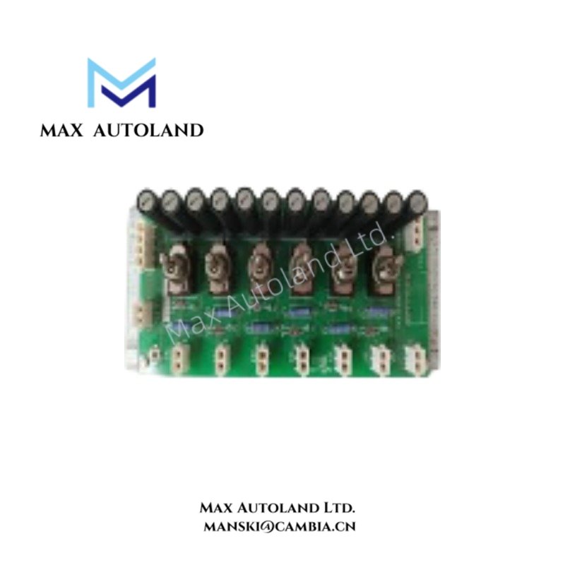
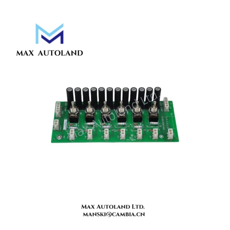
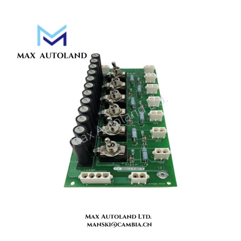
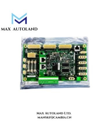
Configured for DC power routing in the GE Mark VI Speedtronic control system, the GE IS200JPDDG1AAA (IS200JPDDG1A Power Distribution Board) distributes specified control-system voltage lines through protected electrical circuits. The board uses onboard fusing to provide circuit protection for connected power distribution paths.
Hardware Specifications
| Parameter | Specification |
|---|---|
| Model | IS200JPDDG1AAA |
| Base Model | IS200JPDDG1A |
| Brand | General Electric (GE) |
| Product Series | Mark VI Speedtronic |
| Product Type | Power Distribution Board |
| Origin | Not specified in supplied data |
| Weight | Approx. 1.0 kg / 2.2 lb |
| Dimensions | Approx. 6.4 x 6.4 x 4.8 in / 16 x 16 x 12 cm |
| Operating Temp | 0 deg C to 60 deg C |
| Supported Voltage Lines | 125 VDC, 48 VDC, 24 VDC |
| Fuse Protection | Onboard fuses |
| Typical Fuse Rating | 15 A, 250 V |
| Fuse Dimensions | 0.25 x 0.25 in |
| Conformal Coating | Specified |
DC Power Distribution and Circuit Protection
The JPDD board routes multiple DC voltage lines within the control cabinet. It supports 125 VDC, 48 VDC, and 24 VDC distribution paths according to the supplied specifications.
In addition, onboard fuses protect individual distribution circuits against excessive current. Therefore, installation should preserve the specified fuse locations and circuit separation. The supplied data identifies a typical 15 A, 250 V fuse rating with a 0.25 x 0.25 in fuse format.
Frequently Asked Questions
Q: What DC voltage levels does the IS200JPDDG1AAA support?
A: The supplied specifications identify 125 VDC, 48 VDC, and 24 VDC distribution lines.
Q: Does the board include circuit protection?
A: Yes. The board uses onboard fuses for circuit protection. The supplied data identifies a typical 15 A, 250 V fuse rating.
Q: Is the IS200JPDDG1AAA a communication or processor board?
A: No. The supplied description identifies it as a Power Distribution Board for electrical power routing rather than a processor or communication interface.
Field Installation Guidelines
- Verify the board identification and terminal assignments against the applicable Mark VI system documentation before installation.
- Isolate the associated power source before connecting or disconnecting the board.
- Confirm the incoming DC voltage before energizing the distribution circuit.
- Maintain the specified fuse type and rating when replacing protective devices.
- Keep power wiring separated from low-level signal and communication wiring where the cabinet design requires it.
- Secure conductors to prevent mechanical stress on terminals and board-mounted connections.
- Inspect connectors, fuse holders, and PCB surfaces for contamination or physical damage before energization.
- Follow the cabinet grounding and bonding scheme specified for the complete Mark VI installation.


