Overview
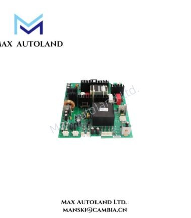
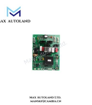
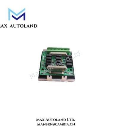
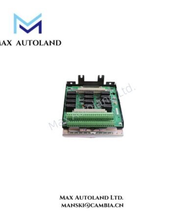
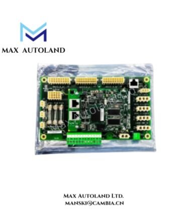
Configured for backup protection signal interfacing in the GE Mark VIe excitation system, the GE IS200SPROH1ADD (IS200SPROH1A Backup Protection Terminal Board) provides direct electrical termination between field voltage signals, the PPRO I/O pack, and the backup trip relay interface. The board conditions speed-related inputs and supports communication between the SPRO terminal board and the integrated PPRO pack.
Hardware Specifications
| Parameter | Specification |
|---|---|
| Model | IS200SPROH1ADD |
| Base Model | IS200SPROH1A |
| Brand | General Electric (GE) |
| Series | Mark VIe |
| Product Type | Backup Protection Terminal Board |
| Application | Mark VIe backup protection and excitation system |
| Origin | United States of America (USA) |
| Operating Temp | -30 to 65 deg C |
| I/O Pack Interface | PPRO I/O pack connection |
| Voltage Inputs | Bus and generator voltage inputs through two potential transformers |
| Backup Trip Interface | DC-37 pin connector |
| Terminal Configuration | 24 barrier terminals in a pluggable block configuration for SPROH1A |
| Availability | In Stock |
GE Industrial Control and I/O Interface Characteristics
The SPRO terminal board works with a PPRO I/O pack to condition speed signal inputs for the programmable protective relay output function. The PPRO pack also communicates with the SPRO board through its dedicated interface.
In addition, the board incorporates two potential transformers for bus and generator voltage inputs. These transformers provide the voltage signal interface required by the backup protection circuitry.
The board also provides a DC-37 pin connector beside the PPRO pack connection. This connector accepts the cable interface to a Mark VIe backup trip relay terminal board. Therefore, the SPRO assembly provides both field termination and inter-board signal routing within the backup protection architecture.
The SPROH1A variant uses 24 barrier terminals arranged in a pluggable terminal block. This configuration supports field wiring access and board-level maintenance.
Frequently Asked Questions
Q: What type of voltage inputs does the IS200SPROH1ADD handle?
A: The board includes two potential transformers for bus and generator voltage input signals.
Q: How does the SPRO board connect to the PPRO system?
A: The SPRO terminal board provides a dedicated connection for the PPRO I/O pack, which conditions speed signal inputs and communicates with the terminal board.
Q: What is the purpose of the DC-37 connector?
A: The DC-37 connector provides the cable interface to a Mark VIe backup trip relay terminal board.
Field Installation Guidelines
Install the board only in the cabinet position and terminal arrangement specified by the applicable GE Mark VIe system documentation.
Before wiring, isolate the associated equipment and verify that the field circuits are de-energized. Confirm terminal identification against the system wiring documentation before applying voltage signals.
Route voltage and control wiring according to the cabinet wiring design. Keep signal wiring separated from high-current power conductors where the installation design requires signal-noise control.
Connect the bus and generator voltage circuits to the designated transformer input terminals. Verify polarity, phase identification, and terminal assignments before commissioning.
When installing the PPRO I/O pack, confirm connector alignment and mechanical seating before energizing the system. Do not force the connector into position.
Use the DC-37 interface only with the specified backup trip relay terminal board cable assembly. Secure the connector and cable to prevent mechanical loading on the PCB connector.
For shielded signal cables, terminate the shield according to the Mark VIe cabinet grounding design. Avoid creating unintended ground loops through multiple shield termination points.
After installation, inspect terminal tightness, connector seating, cable routing, and PCB condition before applying system power.