

Overview
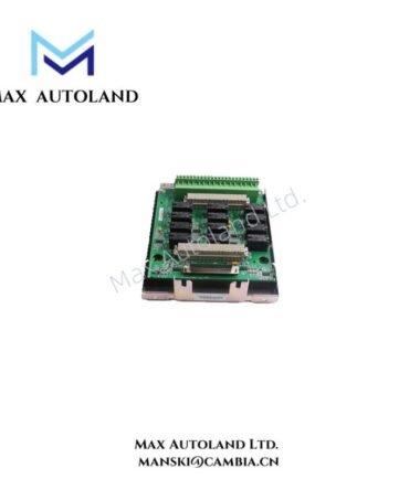
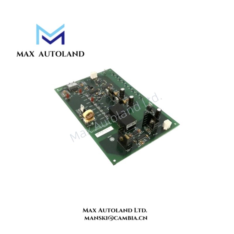
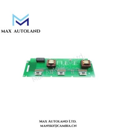
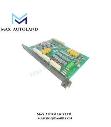
The General Electric IS200EDCFG1A, also cataloged as the IS200EDCFG1A Exciter DC Feedback Board, measures field voltage and field current at the silicon-controlled rectifier (SCR) bridge in the EX2100 excitation control system. It conditions these feedback signals and transmits the corresponding data to the EISB board through fiber-optic links. The board uses an external 24 VDC supply and provides power-status indication through a green PSOK LED.
Hardware Specifications
| Parameter | Specification |
|---|---|
| Model | IS200EDCFG1A |
| Brand | General Electric (GE) |
| Series | EX2100 |
| Product Type | Exciter DC Feedback Board |
| Functional Role | Field voltage and field current feedback |
| Signal Interface | Fiber-optic communication to EISB board |
| Field Current Measurement | DC shunt; maximum input signal 500 mV |
| Amplifier Output Range | -5 V to +5 V |
| Field Voltage Scaling | Seven selectable settings using jumpered resistors |
| Power Supply | External 24 VDC |
| Internal Supply Rails | +15 VDC, -15 VDC, +5 VDC |
| Status Indicator | Green PSOK LED |
| Operating Temp | -30 to 65 deg C |
| Weight | 0.24 kg |
| Dimensions | 23 x 15.3 x 3.2 cm (estimated shipping dimensions) |
| Origin | USA |
| Manual | GEI-100464A |
EX2100 Feedback Signal Conditioning and Fiber-Optic Communication
The IS200EDCFG1A processes two feedback paths associated with the SCR bridge.
- Field voltage feedback: The circuit monitors the bridge negative terminal and the current shunt positive terminal. Jumpered resistors select the voltage scaling configuration. A differential amplifier conditions the signal and drives a voltage-controlled oscillator.
- Field current feedback: A DC shunt produces a low-level signal up to 500 mV. A differential amplifier converts this input into a voltage ranging from -5 V to +5 V for the voltage-controlled oscillator.
- Fiber-optic transmission: The board communicates with the EISB board through optical links. Plastic optical fiber supports distances up to 10 m, while hard-clad silica fiber supports distances up to 90 m, according to the supplied technical description.
- Power monitoring: An external 24 VDC supply feeds onboard regulators that generate +15 VDC, -15 VDC, and +5 VDC. The green PSOK LED indicates power-supply status.
The optical interface provides electrical isolation between the feedback board and the receiving control-panel circuitry. Confirm the applicable fiber type, connector arrangement, and link distance against the system documentation before installation.
Frequently Asked Questions
Q: What signals does the IS200EDCFG1A measure?
A: It measures field voltage and field current at the EX2100 SCR bridge. The current feedback input comes from a DC shunt with a maximum signal of 500 mV.
Q: How does the IS200EDCFG1A communicate with the EISB board?
A: It transmits feedback signals through fiber-optic links. The supplied documentation specifies plastic fiber for distances up to 10 m and hard-clad silica fiber for distances up to 90 m.
Q: What power supply does the board require?
A: The board uses an external 24 VDC supply. Onboard regulators generate +15 VDC, -15 VDC, and +5 VDC. The PSOK LED indicates power-supply status.
Field Installation Guidelines
- Verify identification: Confirm the complete IS200EDCFG1A model number and board revision against the EX2100 equipment documentation.
- Isolate power: Follow the approved excitation-system shutdown and electrical isolation procedures before removing or installing the board.
- Check field feedback wiring: Verify the DC shunt connections, field voltage sensing points, and jumper settings against the applicable GE manual.
- Inspect fiber-optic connections: Confirm fiber type, connector compatibility, routing, and link distance. Avoid sharp bends, crushing, and contamination of optical end faces.
- Verify power connections: Confirm the external 24 VDC supply polarity and wiring before energization. Do not assume that the board is hot-swappable.
- Check status indication: After approved startup, verify the PSOK LED and inspect the EX2100 diagnostics for feedback or communication faults.
- Validate feedback signals: Compare measured field voltage and current feedback against approved commissioning values before returning the excitation system to service.