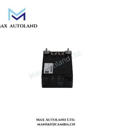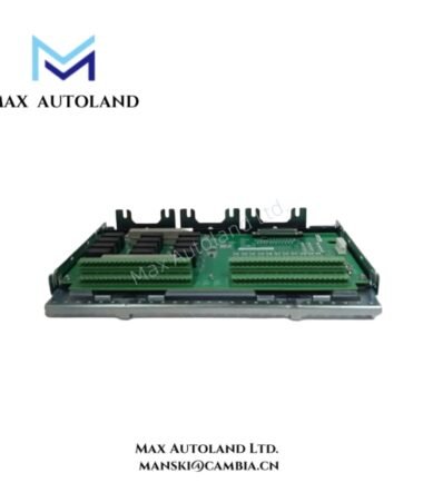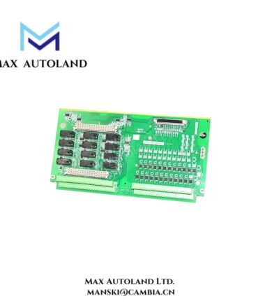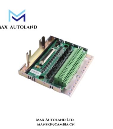


Overview
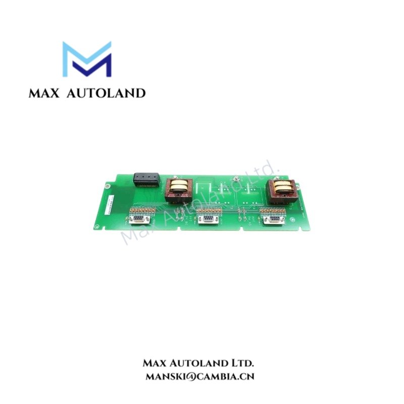
Configured for exciter AC voltage and current measurement in GE EX2100 excitation control systems, the GE IS200EACFG1A (IS200EACFG1A Exciter AC Feedback Board) acquires electrical feedback signals from the exciter power supply and routes measurement signals to the control system through dedicated connectors and the EBKP backplane interface. The supplied documentation identifies three-phase voltage measurement inputs and flux or air-core coil inputs. Compatibility with specific EX2100 and EX2100e configurations should be verified against the applicable hardware documentation.
Hardware Specifications
| Parameter | Specification |
|---|---|
| Model | IS200EACFG1A |
| Brand | GE |
| Product Series | EX2100 Excitation Control System |
| Board Type | Exciter AC Feedback (EACF) Board |
| Input Voltage Range | Up to 480 Vrms, as specified in the supplied description |
| Operating Frequency | 50/60 Hz |
| Voltage Measurement | Three-phase AC voltage sensing |
| Potential Transformer Outputs | Nominal 1.6 Vrms secondary output, as specified in the supplied description |
| Flux / Air-Core Coil Inputs | TB4; stated input range of 0 to 0.8 Vrms |
| Voltage Input Connections | TB1, TB2, TB3 |
| Controller Signal Connections | J504, J509, J514 |
| Backplane Interface | EX2100 EBKP |
| Controller Signal Distribution | M1, M2, and C controller connections, as described in the supplied data |
| Noise Suppression | Input-side high-frequency filtering, as described in the supplied data |
AC Feedback Signal Conditioning and Backplane Interface
The IS200EACFG1A handles electrical measurement signals rather than direct generator excitation power switching. Its input circuits acquire AC voltage and flux-coil signals for use by the excitation control system.
- Voltage measurement: TB1, TB2, and TB3 are identified as voltage input terminals in the supplied description. Confirm phase assignments and permissible input connections using the applicable GE wiring documentation.
- Flux-coil measurement: TB4 is identified for two flux or air-core coil inputs. Verify the sensor type, polarity, and signal range before connection.
- Controller interfaces: J504, J509, and J514 are described as 9-pin sub-D connectors carrying signals toward the M1, M2, and C controllers through the EBKP backplane arrangement.
- Industrial noise control: Keep measurement wiring separated from high-current switching conductors. Terminate cable shields according to the equipment grounding design and GE installation instructions.
- Hardware compatibility: Confirm the board revision, backplane configuration, connector pin assignments, and controller interface before installing a replacement.
The stated signal ranges and connector assignments are based on the supplied description and should be checked against the official board documentation before commissioning.
Frequently Asked Questions
Q: Can the IS200EACFG1A accept three-phase inputs up to 480 Vrms?
A: The supplied description specifies an input voltage capability of up to 480 Vrms for the G1 version. Verify the exact terminal configuration, phase-to-phase or phase-to-ground rating, and approved wiring arrangement before applying voltage.
Q: Does the IS200EACFG1A communicate directly with the excitation controller over Ethernet?
A: The supplied description identifies dedicated 9-pin sub-D connections and an EBKP backplane interface. It does not establish an Ethernet interface. Follow the documented controller connection scheme.
Q: Can the IS200EACFG1A be replaced while the excitation system is energized?
A: Hot-swap capability is not established by the supplied information. Follow GE maintenance procedures and isolate the relevant electrical sources before removing or installing the board.
Field Installation Guidelines
- Verify the hardware: Check the complete IS200EACFG1A part number, board revision, system configuration, and approved replacement compatibility.
- Isolate electrical sources: Apply the site’s lockout/tagout procedure and verify that relevant input terminals are de-energized before handling the board.
- Inspect the mounting and connectors: Check the board, terminal blocks, sub-D connectors, and mating backplane for mechanical damage or contamination.
- Route measurement cables correctly: Separate low-level feedback wiring from high-current conductors and switching circuits to limit electromagnetic interference.
- Ground cable shields: Use the specified shield termination and chassis-grounding arrangement. Avoid creating unintended ground loops.
- Verify wiring before energization: Confirm phase assignments, polarity, terminal references, connector pinouts, and input ratings against the approved wiring diagrams.
- Perform functional checks: After installation, verify the measured AC feedback signals and controller diagnostics in accordance with the site commissioning procedure.