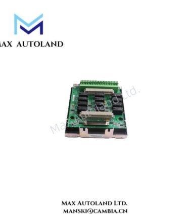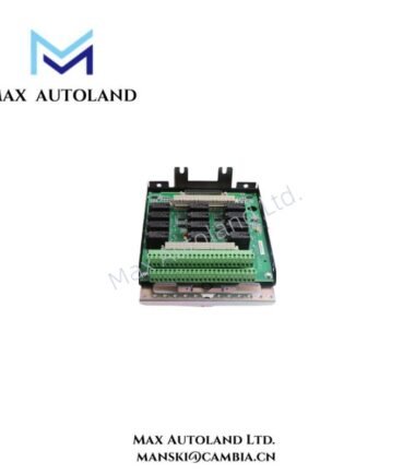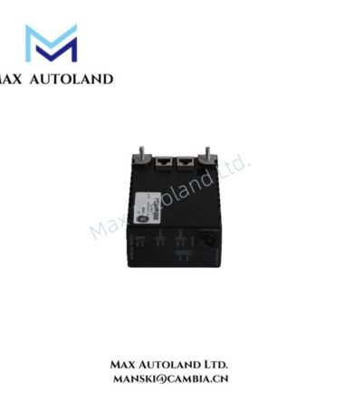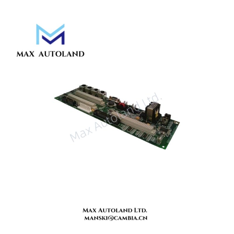
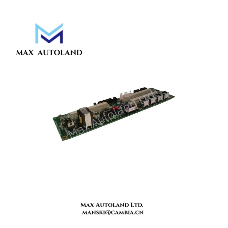
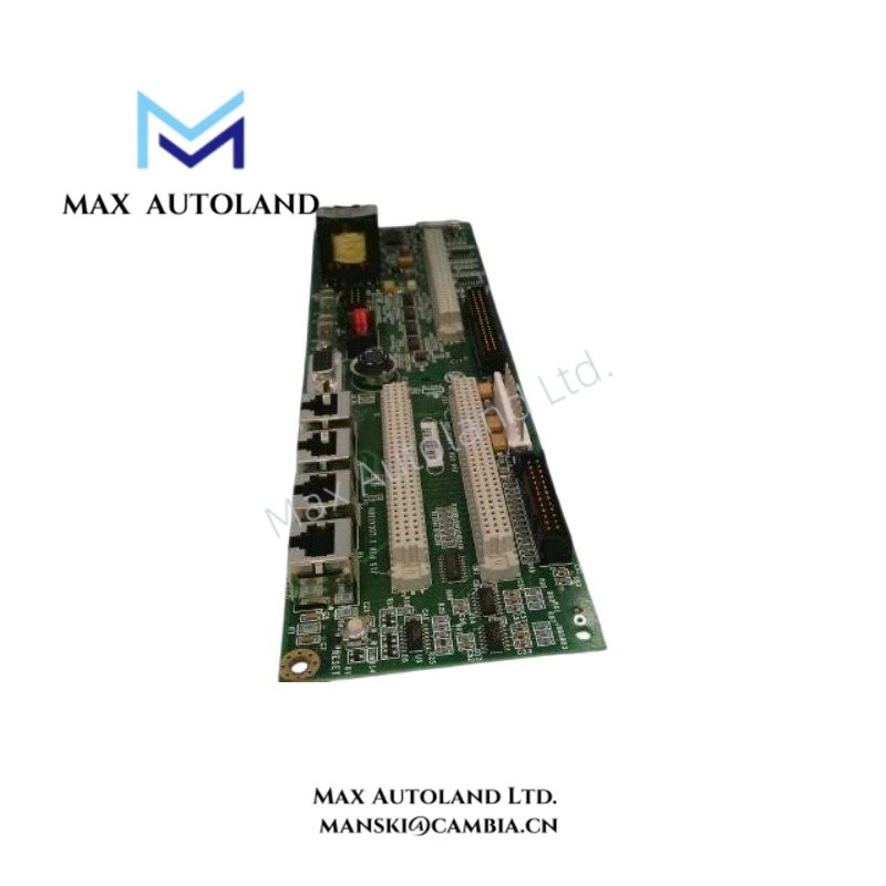
Overview
The General Electric IS200AEPBH1BB, also identified by the base model AEPB, is described as an analog exciter protection and interface board for GE Mark VI turbine control systems. Its exact signal-processing functions, electrical interfaces, and compatibility with Mark VIe require confirmation against manufacturer documentation. No verified electrical ratings or dimensional data are available in the supplied information.
Hardware Specifications
| Parameter | Specification |
|---|---|
| Model | IS200AEPBH1BB |
| Base Model | AEPB |
| Brand | General Electric (GE) |
| Product Series | Mark VI (reported; Mark VIe compatibility unverified) |
| Product Type | Exciter Protection Board (reported; exact designation requires verification) |
| Primary Function | Analog exciter protection and interface (reported) |
| Application | Turbine generator excitation control |
Excitation Signal Interface and Protection
The supplied description identifies the IS200AEPBH1BB as an analog exciter protection and interface component. However, it does not establish the board’s specific analog input and output channels, voltage ranges, current ratings, or protection thresholds.
Before integrating this board into an excitation control system, engineers should verify the terminal assignments, signal scaling, electrical isolation, and protection functions against the applicable GE hardware documentation. Do not assume that the board supports particular feedback loops or fault-detection functions without a confirmed schematic or technical manual.
Frequently Asked Questions
Q: Is the IS200AEPBH1BB compatible with both Mark VI and Mark VIe systems?
A: The supplied description mentions both platforms, but it does not provide a manufacturer compatibility statement. Verify the board’s complete part number, hardware revision, rack configuration, and system documentation before installation.
Q: What are the operating voltage and power consumption of the IS200AEPBH1BB?
A: The available information does not specify supply voltage, current draw, or power consumption. Confirm these values using the applicable hardware manual or board-level electrical documentation before energizing the assembly.
Q: Does the IS200AEPBH1BB support hot swapping?
A: Hot-swap capability is not established by the supplied information. Follow the system-specific maintenance procedure and isolate power as required before removing or installing the board.
Field Installation Guidelines
- Verify identification: Check the complete IS200AEPBH1BB part number and revision markings against the equipment bill of materials.
- Confirm compatibility: Check the approved rack, connector arrangement, and system configuration before installation.
- Isolate power: Apply the equipment manufacturer’s electrical isolation and lockout procedures before handling the board.
- Inspect connectors: Check connector contacts, board edges, and mating interfaces for contamination or physical damage.
- Route wiring correctly: Separate low-level analog signal wiring from high-current conductors and switching power circuits where applicable. Follow the cabinet’s wiring and shielding requirements.
- Verify grounding: Apply the manufacturer’s grounding and cable-shield termination instructions. Do not assume a universal shield termination arrangement.
- Perform functional checks: After installation, verify system diagnostics, signal readings, and protection functions using approved commissioning procedures.