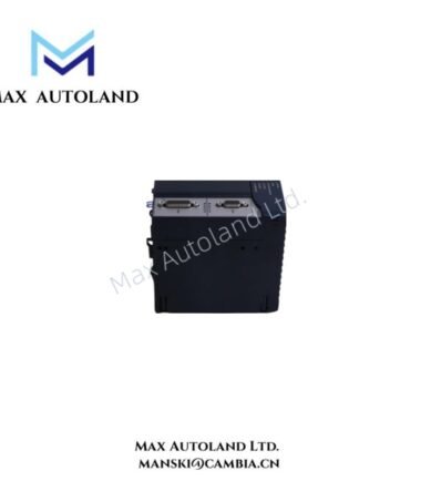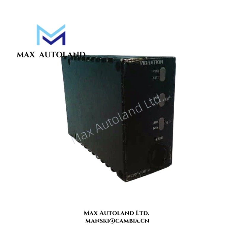
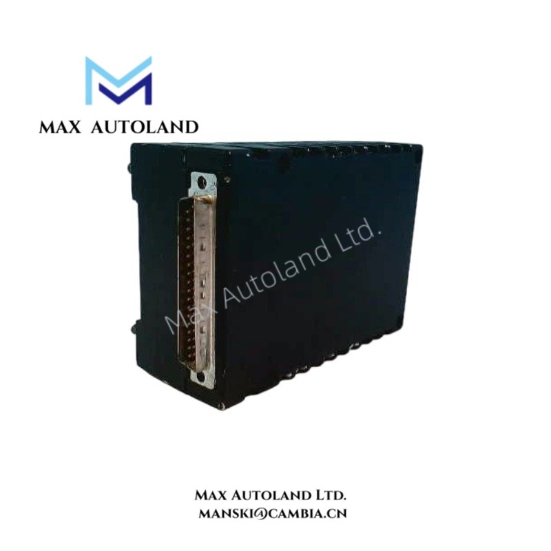
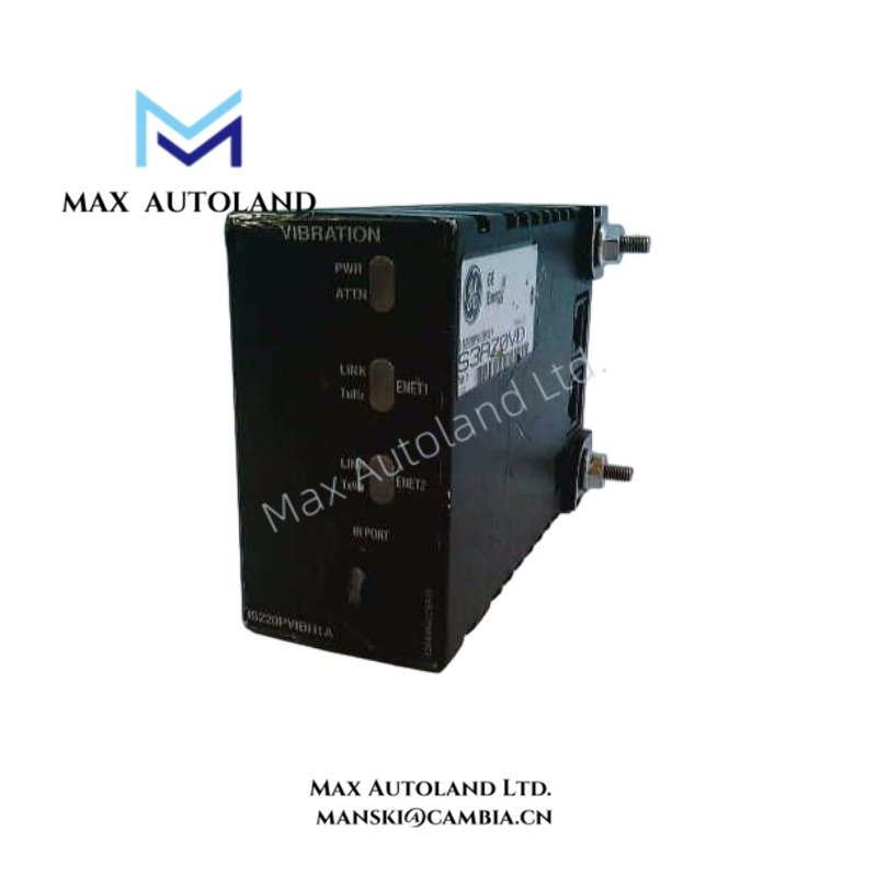

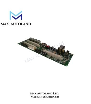
Overview
The General Electric ISP220PTURH1A, also identified by the base model ISP220PTURH1A, is a turbine input/output (I/O) module associated with turbine control and protection functions. It handles electrical inputs associated with turbine trip requests, emergency stop signals, and speed detection. The supplied specifications identify a 27.4 to 28.6 VDC power input and separate voltage ranges for TRPA and emergency stop inputs.
Hardware Specifications
| Parameter | Specification |
|---|---|
| Model | ISP220PTURH1A |
| Brand | General Electric (GE) |
| Series | Turbine Control; exact platform compatibility requires verification |
| Product Type | Turbine I/O Module |
| Origin | United States (as supplied; verify against unit label) |
| Power Supply Input | 27.4 to 28.6 VDC |
| TRPA Input Voltage Range | 16 to 140 VDC |
| E-Stop Input Range | -15 to +15 VDC |
| Speed Input Voltage | 28 VDC |
| Primary Function | Turbine input signal handling and trip-related interface |
| Application | Turbine control and protection |
Turbine Signal Interface and Control Compatibility
The listed electrical ranges distinguish the module’s power supply from its trip-related and emergency stop inputs. Therefore, installation requires verification of the applicable terminal assignments and input circuit requirements.
The TRPA input range is specified as 16 to 140 VDC. The emergency stop input range is specified as -15 to +15 VDC. Meanwhile, the speed input is listed at 28 VDC. These values describe different electrical interfaces and must not be treated as interchangeable.
For integration into a GE turbine control system, confirm the exact hardware revision, terminal configuration, and controller compatibility against the manufacturer’s documentation. The supplied information does not establish a specific Mark VIe compatibility designation, communication protocol, channel count, or redundancy architecture.
Frequently Asked Questions
Q: What power supply does the ISP220PTURH1A require?
A: The supplied specification lists a power supply input of 27.4 to 28.6 VDC. Confirm the permitted supply conditions and terminal polarity using the applicable hardware documentation.
Q: What voltage range applies to the TRPA input?
A: The supplied data specifies 16 to 140 VDC for the TRPA input. Verify the input circuit type and terminal assignment before connecting field wiring.
Q: Can the ISP220PTURH1A be hot-swapped during operation?
A: Hot-swap support is not established by the available specifications. Check the manufacturer’s installation instructions and system maintenance procedures before removing or replacing the module under power.
Field Installation Guidelines
- Verify the hardware: Check the complete model number, revision markings, and system compatibility before installation.
- Confirm terminal assignments: Use the applicable wiring diagram to distinguish power supply, TRPA, emergency stop, and speed input connections.
- Check electrical levels: Confirm that each field signal matches the specified input range. Do not apply the TRPA voltage range to other inputs without documented approval.
- Route wiring appropriately: Separate low-level signal wiring from power conductors where practical to reduce electrical interference.
- Manage cable shielding: Follow the manufacturer’s grounding instructions and the plant’s grounding standards. Avoid introducing unintended ground loops.
- Inspect before energizing: Check terminal tightness, conductor condition, polarity, and wiring continuity before applying power.
- Validate protection circuits: Perform approved commissioning checks for trip and emergency stop circuits under the site’s safety procedures.
- Confirm replacement requirements: Verify firmware, hardware revision, configuration, and system compatibility before replacing an installed unit.