Overview
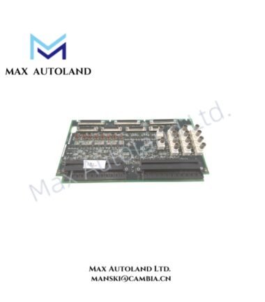
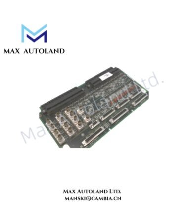
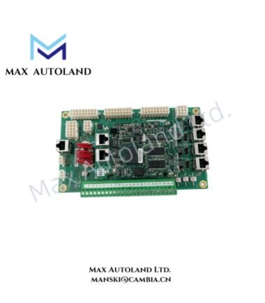
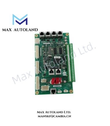
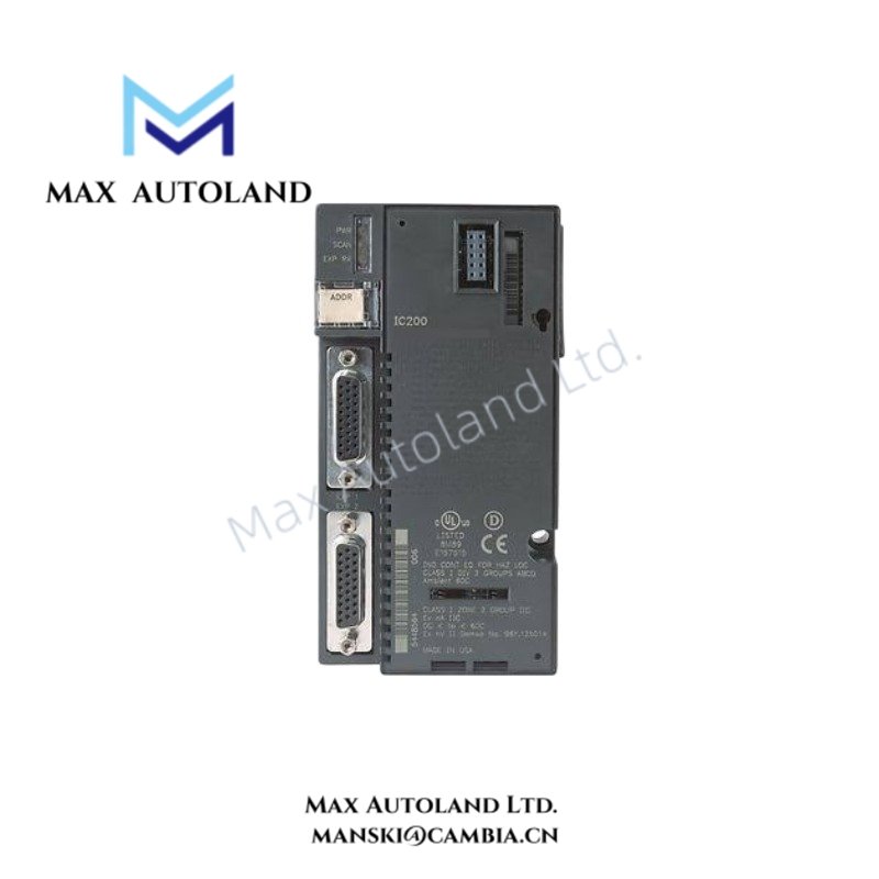
Configured for PLC program execution, discrete and analog I/O processing, and serial data communication in GE Fanuc VersaMax PLC systems, the GE Fanuc IC200CPU001 (IC200CPU001 CPU Module) provides direct physical and electrical execution through the VersaMax backplane and connected field I/O network. The CPU stores user application data, executes Boolean instructions, exchanges serial data, and coordinates I/O operation through the local PLC architecture.
Hardware Specifications
| Parameter | Specification |
|---|---|
| Model | IC200CPU001 |
| Brand | GE Fanuc |
| Product Line | VersaMax PLC Series |
| Product Type | CPU Module |
| Power Consumption | Backplane current: 140 mA at 5 VDC; 100 mA at 3.3 VDC |
| User Memory | 34 KB configurable memory |
| Memory Storage | Flash memory and battery-backed RAM |
| Boolean Execution Speed | 1.8 ms / K instructions typical |
| Discrete Inputs | Up to 2048 points |
| Discrete Outputs | Up to 2048 points |
| Discrete Internal Bits | 1024 points |
| Discrete Temporary Bits | 256 points |
| Global Discrete Bits | 1280 points |
| Modbus Registers | 32 |
| Communication Port 1 | RS-232 |
| Communication Port 2 | RS-485 |
| Supported Protocols | SNP Slave, Modbus RTU Slave, Serial I/O |
| Programming Languages | Ladder Diagram and Instruction List |
| Additional Functions | Floating-point math, override functions, battery-backed RTC |
| Mounting | DIN rail or panel mount |
VersaMax Backplane Communication and I/O Scaling
The GE Fanuc IC200CPU001 communicates with the VersaMax PLC hardware through the system backplane. The CPU coordinates application execution with connected I/O modules and manages the configured I/O data structure.
The module supports I/O density scaling through expansion hardware while maintaining centralized CPU program execution. Its Flash-based storage retains application information without continuous operating power, while battery-backed RAM supports retained data functions and the Real-Time Clock.
Firmware and application compatibility should be verified against the installed VersaMax hardware configuration before system commissioning or CPU replacement.
Frequently Asked Questions
Q: What power load does the IC200CPU001 place on the VersaMax backplane?
A: The IC200CPU001 draws 140 mA at 5 VDC and 100 mA at 3.3 VDC from the backplane. The total power budget should include all installed CPU and I/O modules.
Q: Does the IC200CPU001 provide serial communication interfaces?
A: Yes. The CPU includes one RS-232 port and one RS-485 port. Supported functions include SNP Slave, Modbus RTU Slave, and Serial I/O communication.
Q: How should application memory be retained during power interruption?
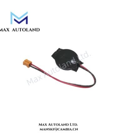
A: The CPU uses Flash memory and battery-backed RAM. Battery condition and memory retention requirements should be checked during maintenance according to the installed system configuration.
Field Installation Guidelines
Install the GE Fanuc IC200CPU001 on the specified VersaMax DIN rail or panel mounting arrangement and ensure that the module fully engages with the associated backplane connections.
Disconnect or isolate system power before installing or removing the CPU unless the applicable system documentation specifically permits the procedure. Do not force the module into the backplane connector.
Route RS-232 and RS-485 communication cables separately from high-current power conductors and motor wiring where practical. Apply the required cable shielding and grounding method according to the system installation design.
Calculate the total backplane current requirement before energizing the PLC system. Include the CPU and all installed I/O modules in the power budget. After installation, verify CPU startup status, I/O communication, serial port configuration, and application memory operation before placing the system into service.