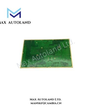
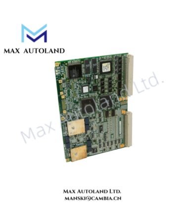
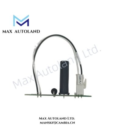
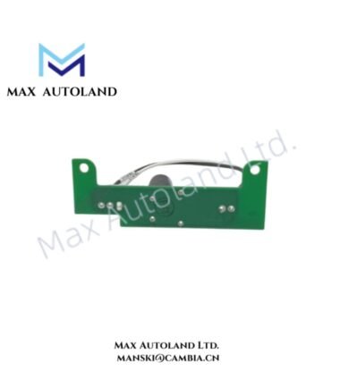
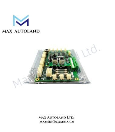
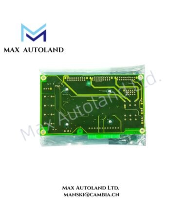
Overview
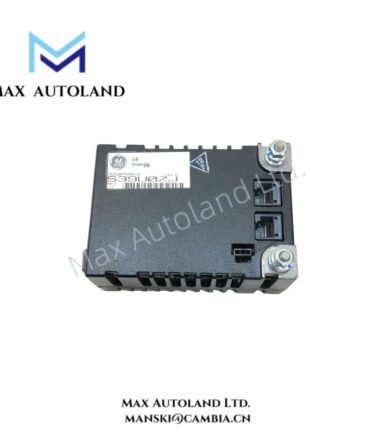
Configured for electrohydraulic servo valve interfacing and feedback signal termination in the GE Speedtronic Mark VI control system, the GE IS200TSVOH1B (IS200TSVOH1B Servo Terminal Board) provides direct physical and electrical execution. The board connects servo control circuits with field-mounted electrohydraulic devices and supports servo current inputs, feedback signals, and protective servo clamping functions during turbine trip conditions.
Hardware Specifications
| Parameter | Specification |
|---|---|
| Model | IS200TSVOH1B |
| Brand | General Electric (GE) |
| Product Series | Speedtronic Mark VI |
| Product Type | Servo Terminal Board |
| Product Parameters | Termination BD., Servo |
| Assembly Level | IS200 |
| Application Type | Simplex |
| Board Revision | B |
| Origin | United States (USA) |
| Servo Valve Support | Up to two electrohydraulic servo valves |
| Servo Current Inputs | Dual servo current sources |
| Feedback Inputs | Up to three LVDT or LVDR feedback sensor attachments per channel |
| Feedback Selection | High, median, or low select configuration |
| Pulse Rate Inputs | 2 to 14 kHz |
| Active PR Pickup Signal | 5 to 27 V p-p into 60 kOhm |
| Terminal Type | Barrier-type terminal blocks |
| Protective Function | Integrated servo valve clamp function |
| Coating Style | Conformal coating |
| System Interface | GE Speedtronic Mark VI control system |
Mark VI I/O and Hardware Interface Characteristics
The IS200TSVOH1B operates as a field termination interface within the Mark VI turbine control architecture. It provides organized electrical connections between the control system and electrohydraulic servo equipment while routing feedback signals to the associated control circuitry.
The board configuration supports I/O density scaling by consolidating servo command and feedback connections on a dedicated termination assembly. In addition, the terminal board architecture separates field wiring from the primary control electronics, which supports inspection and maintenance of field-side connections.
The integrated servo clamp function acts during applicable turbine trip conditions to place the servo control circuit into its intended protective state. Therefore, installation and replacement procedures should verify field wiring identity and feedback channel assignments before the board enters service.
Frequently Asked Questions
Q: What is the primary function of the GE IS200TSVOH1B?
A: The IS200TSVOH1B provides field termination and electrical interfacing for electrohydraulic servo valves and associated feedback circuits in a GE Speedtronic Mark VI control system.
Q: How many servo valves can the IS200TSVOH1B support?
A: The provided specifications indicate support for up to two electrohydraulic servo valves through the board’s servo interfacing circuits.
Q: Does the IS200TSVOH1B include a turbine trip protection function?
A: Yes. The board includes an integrated servo valve clamp function that operates as part of the protective response associated with turbine trip conditions.
Field Installation Guidelines
- Disconnect system power and follow the applicable turbine control maintenance procedure before installing or removing the board.
- Verify the complete model number IS200TSVOH1B and board revision before replacement.
- Connect field conductors to the designated barrier terminals according to the applicable Mark VI wiring documentation.
- Keep servo command wiring separated from high-power conductors to reduce electrical interference.
- Use the specified cable shielding and grounding arrangement for feedback and low-level signal circuits.
- Verify servo valve connections and feedback sensor assignments before energizing the control system.
- Inspect terminal tightness and conductor condition during installation.
- Do not assume unsupported hot-swap capability; isolate power according to the approved maintenance procedure before board replacement.
- After installation, verify servo feedback signals and protective clamp operation using approved commissioning procedures.