
Overview
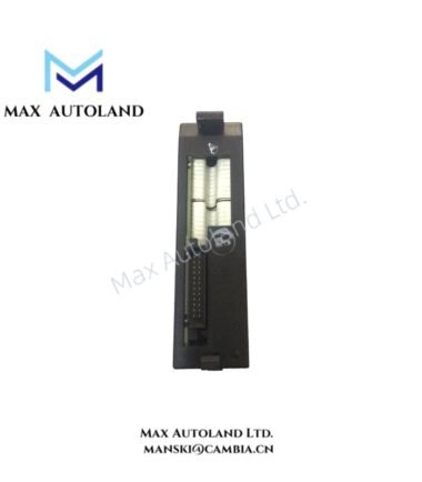
Configured for high-density external wiring from 32-point I/O modules in the Series 90-30 platform, the GE Fanuc Automation IC693CBK001 (IC693CBK001 Cable Kit) provides two 10 ft cables with 24-pin connectors. The kit contains right- and left-end cables for connection to the module interface and field wiring.
Hardware Specifications
| Parameter | Specification |
|---|---|
| Model | IC693CBK001 |
| Brand | GE Fanuc Automation |
| Product Line | Series 90-30 |
| Type | Cable Kit |
| Function | High-density I/O cables |
| Cables | Two; right and left end, IC693CBL327-328 |
| Compatibility | 32-point I/O modules |
| Connector | Fujitsu FCN-365S024-AU |
| Connector Type | 24-pin connector / stripped wire ends |
| Amperage Rating | 1.2 A per conductor |
| Cable Length | 10 ft (3 m) |
| Kits per Module | 1 kit, two cables per module |
| Weight | 2.38 lb (1.08 kg) |
| Product Lifecycle Status | Discontinued / Obsolete |
I/O Density and Backplane Wiring Interface
The IC693CBK001 uses two matching cable assemblies to route the signals from a 32-point Series 90-30 I/O module toward external termination points. Each cable uses a Fujitsu FCN-365S024-AU 24-pin connector at the module interface and provides stripped wire ends for field-side termination.
The 1.2 A rating applies to each conductor. Therefore, field wiring should maintain conductor separation, termination integrity, and appropriate routing for the connected I/O load. The two cables provide right- and left-side connection arrangements while reducing the clearance space required in front of the PLC.
Frequently Asked Questions
Q: How many cables are included in one IC693CBK001 kit?
A: Each kit contains two cables. The supplied cables provide the right- and left-end connections identified as IC693CBL327-328.
Q: What connector does the IC693CBK001 use?
A: The cable kit uses Fujitsu FCN-365S024-AU 24-pin connectors, with stripped wire ends for external wiring.
Q: What is the conductor current rating?
A: Each conductor has a specified amperage rating of 1.2 A.
Field Installation Guidelines
- Verify the I/O module type and connector arrangement before installation.
- Install both cable assemblies according to their designated right- and left-end positions.
- Fully seat each 24-pin connector before securing the cable.
- Route the stripped wire ends to the corresponding field terminals according to the I/O module wiring documentation.
- Keep I/O wiring separated from high-voltage and high-current power conductors where practical.
- Provide strain relief so cable weight and movement do not load the connector.
- Maintain the specified cable routing and avoid excessive bending or mechanical tension.
- Check conductor identification and terminal continuity before energizing the connected I/O circuit.
- Because the supplied data identifies the IC693CBK001 as discontinued/obsolete, verify the replacement or equivalent cable assembly against the installed Series 90-30 I/O module before substitution.