
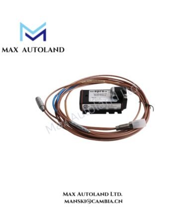
Overview
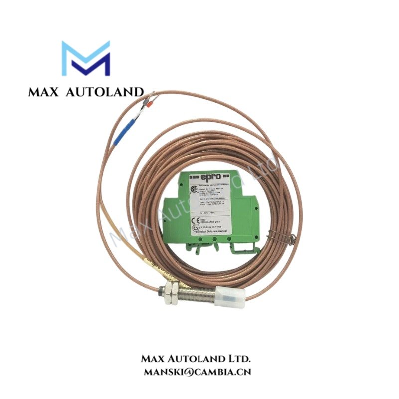
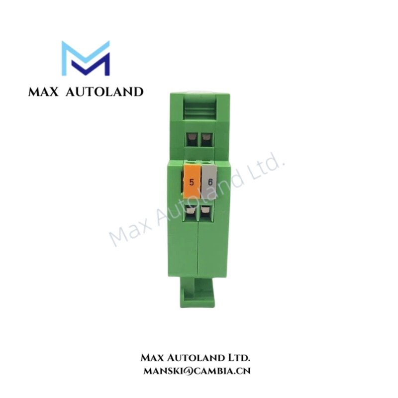
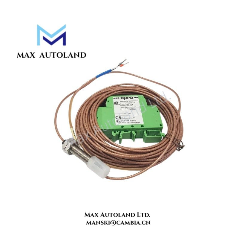
The Emerson Epro PR6423/00C-030, also cataloged under the PR6423 8 mm Eddy Current Sensor series, measures non-contact shaft displacement through electromagnetic induction. The probe converts changes in the distance between its sensing tip and a conductive target into an electrical signal for compatible Epro signal converters and turbomachinery monitoring systems.
Hardware Specifications
| Parameter | Specification |
|---|---|
| Model | PR6423/00C-030 |
| Brand | Emerson Epro |
| Product Type | 8 mm Eddy Current Displacement Transducer |
| Origin | Not specified |
| Weight | Approx. 100 g |
| Dimensions | Not specified |
| Operating Temp | Sensor tip and cable: -35 deg C to +200 deg C |
| Power Consumption | Not specified; supplied through a compatible signal converter |
| Probe Tip Diameter | 8 mm |
| Measurement Range | 2 mm (80 mils) |
| Static Measurement Range | +/- 1.0 mm |
| Dynamic Measurement Range | 0 to 500 um |
| Sensitivity | 8 V/mm (203.2 mV/mil), +/- 5% |
| Linearity Deviation | +/- 0.025 mm (+/- 1 mil) |
| Nominal Air Gap | 0.5 mm (20 mils), as supplied |
| Target Material | Ferromagnetic steel |
| Standard Calibration Material | 42CrMo4 / AISI 4140 |
| Minimum Shaft Diameter | Greater than 25 mm |
| Sensor Tip Material | PEEK |
| Housing Material | Stainless steel |
| Cable Insulation | PTFE |
| Protection Rating | IP66 / IP67, as supplied |
| Cable Configuration | Exact cable and connector configuration requires confirmation |
| Compatible Signal Converters | Epro CON series; verify model-specific compatibility |
Eddy Current Measurement and Signal Conditioning
The PR6423/00C-030 operates as part of a non-contact displacement measurement loop. Its probe tip generates an electromagnetic field that interacts with the conductive shaft surface. Consequently, changes in the probe-to-target distance alter the electrical characteristics of the sensing circuit.
A compatible signal converter processes this response and provides a conditioned measurement output for machinery monitoring equipment.
The stated sensitivity is 8 V/mm, with a linearity deviation of +/- 0.025 mm. However, actual measurement performance depends on the specified calibration target, probe installation, cable configuration, and compatible converter.
For machinery protection applications, technicians should verify the probe gap and converter scaling against the applicable system documentation before commissioning.
Frequently Asked Questions
Q: What physical parameter does the PR6423/00C-030 measure?
A: It measures the relative displacement between the probe tip and a conductive target. In turbomachinery applications, this measurement supports shaft vibration, axial position, radial displacement, and eccentricity monitoring.
Q: Does the PR6423/00C-030 require direct mechanical contact with the shaft?
A: No. The probe uses electromagnetic induction to detect target displacement without physical contact. Therefore, the sensing tip does not require mechanical contact with the rotating shaft.
Q: Can the PR6423/00C-030 connect directly to a PLC analog input?
A: The supplied information does not establish a direct PLC connection. The probe operates within a compatible sensor and signal-conditioning arrangement. Verify the converter output type, electrical interface, and input requirements before connecting it to a PLC or monitoring system.
Field Installation Guidelines
1. Mechanical mounting: Install the probe in a suitable mounting position and maintain adequate clearance from the rotating shaft and surrounding components.
2. Target surface: Confirm that the measurement surface matches the specified ferromagnetic calibration material or the applicable system calibration requirements.
3. Probe gap: Set the initial operating gap according to the compatible converter documentation. Do not assume the stated nominal air gap represents the final commissioning setting.
4. Cable routing: Route the sensor cable away from high-current power conductors, switching devices, and other potential electrical interference sources.
5. Shielding and grounding: Follow the manufacturer’s grounding and cable-shield termination instructions for the complete probe and converter assembly.
6. Signal verification: Before commissioning, confirm cable continuity, connector condition, converter compatibility, and measurement polarity.
7. Environmental protection: Inspect cable insulation, connector sealing, and mounting interfaces to maintain the specified ingress protection conditions.
8. Commissioning: Verify the measurement response against the applicable calibration documentation before enabling machinery monitoring or protection functions.


Reviews
There are no reviews yet.