
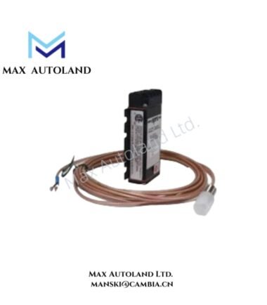
Overview
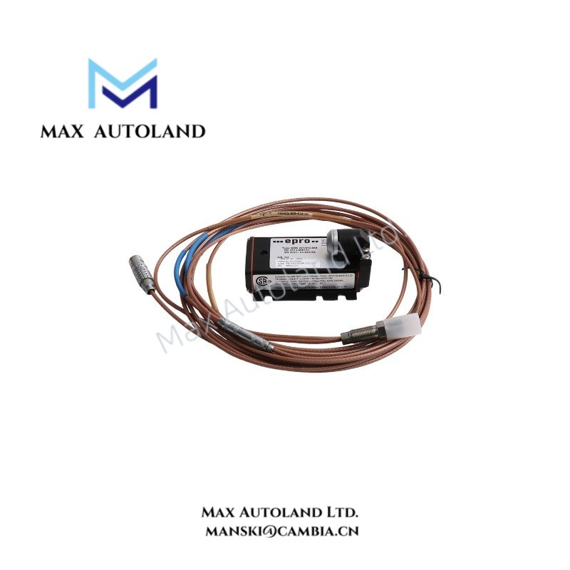
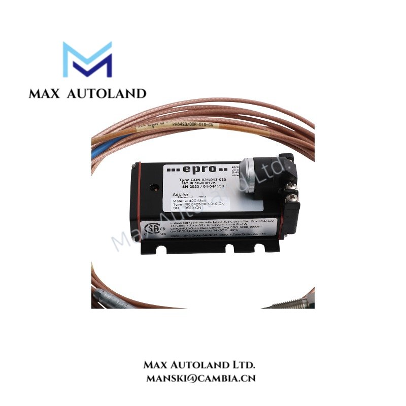
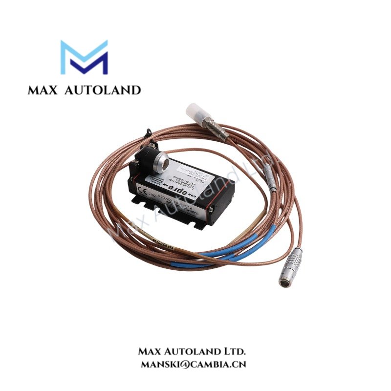
Emerson PR6423/00R-010-CN CON021/913-030 Proximity Sensors
The Emerson PR6423/00R-010-CN CON021/913-030, also cataloged as the PR6423/00R-010-CN CON021/913-030 Proximity Sensors, operates as a dedicated hardware component for non-contact shaft vibration and displacement measurement within turbine supervisory and machinery protection platforms.
Hardware Specifications
| Parameter | Specification |
|---|---|
| Model | PR6423/00R-010-CN CON021/913-030 |
| Brand | Emerson / Epro |
| Origin | Germany |
| Weight | 0.45 kg |
| Dimensions | Probe Diameter: 8 mm nominal; Converter: Standard DIN / panel mount housing |
| Operating Temp | -35 deg C to +180 deg C (Probe head); Converter: -25 deg C to +85 deg C |
| Power Consumption | < 1.5 W nominal |
Measurement Loop and Proportional Gap Voltage
Configured for high-precision displacement tracking, the eddy-current transducer architecture processes high-frequency electromagnetic fields generated by the probe tip coil. As the distance between the reverse-mount probe body and the ferromagnetic steel target changes, the corresponding impedance variation alters the resonant circuit parameters. The matched CON021/913-030 converter translates these physical changes into a proportional gap voltage output. Engineers must calibrate the static gap voltage to nominal operating points—typically around -10 VDC depending on the bias requirements—prior to commissioning the monitoring channel. Furthermore, strict adherence to approved cable routing and shielding protocols ensures that electromagnetic interference from surrounding variable frequency drives or high-voltage lines does not distort the proportional output signal.
Frequently Asked Questions
Q: Can the CON021/913-030 converter be replaced independently of the PR6423/00R-010-CN probe cable assembly?
A: No. The extended-range calibration requires a matched system pairing. Replacing individual components without maintaining the factory-calibrated probe, cable, and converter combination invalidates the linearity class and measurement accuracy.
Q: What is the primary function of the verified static gap before system commissioning?
A: The static gap establishes the baseline linear operating point on the converter output curve, ensuring that rotor vibration amplitudes remain within the 3.0 mm extended measuring range without signal clipping.
Field Installation Guidelines
Ensure the reverse-mount probe body is securely threaded into the machinery housing using appropriate thread sealant while maintaining specified mechanical torque limits. Route the interconnecting signal cable away from high-current power cables and inductive loads to minimize noise pickup. Ground the cable shield properly at the monitoring rack termination point to preserve signal integrity and prevent ground loops across the instrumentation circuit. Verify that the target material consists of approved ferromagnetic steel with a sufficient surface area exceeding the probe tip diameter before initializing static gap checks.


Reviews
There are no reviews yet.