
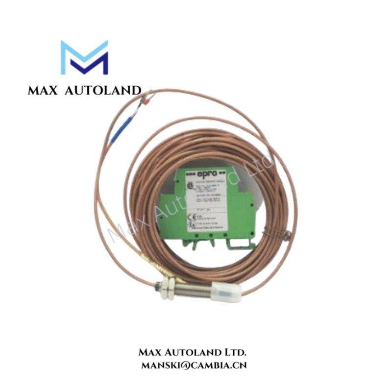
Overview
The Emerson Epro PR6423/004-031-CN, also cataloged within the PR6423 8 mm eddy current sensor family, operates as a non-contact displacement transducer for measuring shaft vibration, axial position, and relative displacement in turbomachinery monitoring systems. It converts changes in the electromagnetic coupling between the probe tip and a conductive target into electrical signals through a compatible Epro signal converter.
Hardware Specifications
| Parameter | Specification |
|---|---|
| Model | PR6423/004-031-CN |
| Brand | Emerson Epro |
| Product Type | 8 mm Eddy Current Sensor / Displacement Transducer |
| Sensor Probe Tip Diameter | 8 mm |
| Measurement Range | 2 mm (80 mils) |
| Static Measurement Range | +/- 1.0 mm |
| Dynamic Measurement Range | 0 to 500 um |
| Initial Air Gap | 0.5 mm (20 mils) |
| Sensitivity | 8 V/mm (203.2 mV/mil) +/- 5% |
| Target Material | Ferromagnetic steel |
| Standard Calibration Material | 42CrMo4 / AISI 4140 |
| Minimum Shaft Diameter | Greater than 25 mm |
| Sensor Operating Temperature | -35 to +180 deg C |
| Connector / Extended Cable Temperature | -35 to +150 deg C |
| Ingress Protection | IP66 / IP67 |
| Sensor Tip Material | PEEK |
| Housing Material | Stainless Steel |
| Cable Insulation | PTFE |
| Compatible Signal Converters | Epro CON011, CON021, CON041 series |
| Power Consumption | Supplied through compatible signal converter; specific consumption not provided |
Eddy Current Measurement and Signal Scaling
The PR6423/004-031-CN operates through electromagnetic induction. Its probe generates an alternating electromagnetic field, which induces eddy currents in the conductive shaft surface.
As the shaft moves relative to the probe, the electromagnetic coupling changes. Consequently, the signal converter produces an electrical output proportional to the measured displacement within the calibrated range.
The specified sensitivity is 8 V/mm, with a tolerance of +/- 5%. Therefore, the converter and monitoring system must use the corresponding calibration characteristics to interpret displacement readings.
For accurate measurement, maintain the specified initial air gap and use a compatible ferromagnetic target material.
Frequently Asked Questions
Q: Which signal converters can interface with the PR6423/004-031-CN?
A: The supplied specifications identify the Epro CON011, CON021, and CON041 series as compatible signal converter families. Confirm the exact probe and converter combination against the applicable manufacturer documentation.
Q: What target material does this sensor require for standard calibration?
A: The stated calibration material is 42CrMo4 / AISI 4140 ferromagnetic steel. Target material differences can affect the measurement response and calibration accuracy.
Q: Can the sensor measure both static displacement and dynamic shaft vibration?
A: Yes. The specified static measurement range is +/- 1.0 mm, while the stated dynamic measurement range is 0 to 500 um. The actual measurement configuration depends on the installed converter and monitoring system.
Field Installation Guidelines
1. Mechanical Mounting: Secure the probe using its designated mounting arrangement. Avoid excessive mechanical loading on the probe housing or integral cable.
2. Air Gap Adjustment: Position the probe relative to the shaft target according to the specified initial air gap of 0.5 mm. Verify the gap using the applicable installation procedure.
3. Target Surface: Confirm that the measurement surface uses compatible ferromagnetic material. Check the shaft surface for deposits, damage, or irregularities that could affect the measurement.
4. Cable Routing: Route the sensor cable separately from high-power switching conductors where practical. Avoid sharp bends, crushing, and excessive tensile loading.
5. Electrical Connection: Connect the probe to a compatible Epro signal converter. Verify connector compatibility and wiring assignments before energizing the monitoring circuit.
6. Shielding and Grounding: Follow the manufacturer’s grounding and shielding arrangement. Avoid unintended ground loops and maintain separation from sources of electromagnetic interference.
7. Environmental Protection: Confirm that the installed configuration maintains the required ingress protection. Inspect connectors and cable interfaces for damage before commissioning.
8. Commissioning: Verify the converter output, initial gap condition, and measurement response against the applicable system calibration documentation.


Reviews
There are no reviews yet.