
Overview
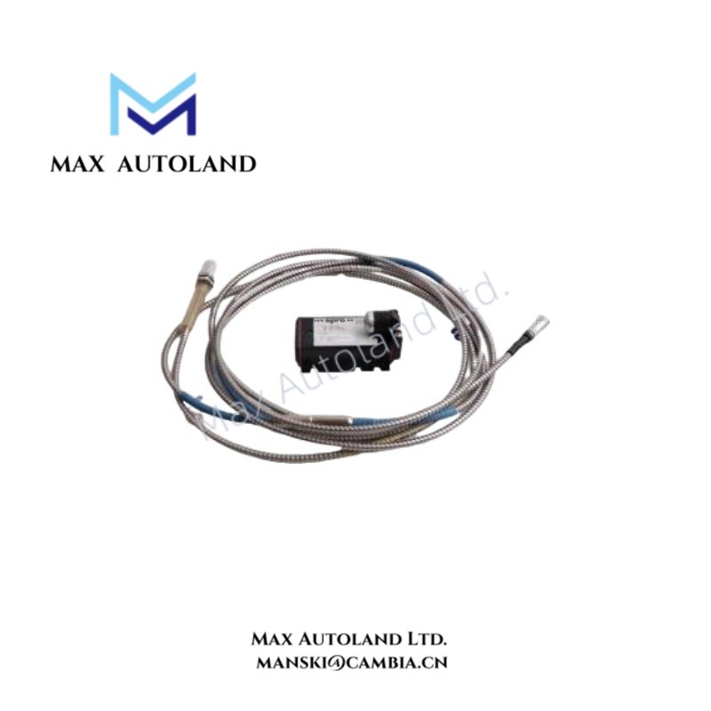
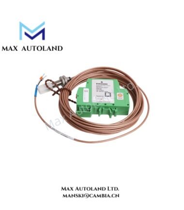
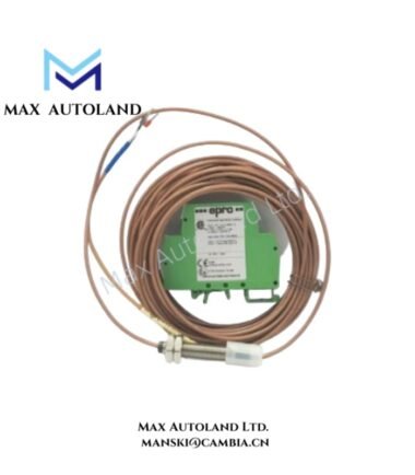
The Emerson Epro PR6423/004-000, also identified by the base model PR6423, is an 8 mm eddy current proximity sensor. It measures the relative displacement between the probe tip and a conductive shaft target through electromagnetic induction. The sensor provides dynamic and static displacement signals for compatible Epro signal converters and turbomachinery monitoring systems.
Hardware Specifications
| Parameter | Specification |
|---|---|
| Model | PR6423/004-000 |
| Brand | Emerson Epro |
| Product Type | 8 mm Eddy Current Proximity Sensor |
| Operating Temp | -35 deg C to +180 deg C (sensor tip and cable) |
| Power Consumption | Supplied through a compatible signal converter; exact consumption not specified |
| Probe Tip Diameter | 8 mm |
| Measurement Principle | Non-contact eddy current displacement measurement |
| Linear Measurement Range | 2 mm (80 mils), as provided |
| Dynamic Measurement Range | 0 to 500 um, as provided |
| Sensitivity | 8 V/mm (203.2 mV/mil), +/- 5%, as provided |
| Target Material | Ferromagnetic steel |
| Calibration Material | 42CrMo4 / AISI 4140 |
| Initial Air Gap | 0.5 mm to 1.0 mm, as provided |
| Protection Rating | IP66 / IP67, as provided |
| Probe Tip Material | PEEK, as provided |
| Housing Material | Stainless steel, as provided |
| Signal Interface | Compatible Epro signal converter |
| Compatible Converter Examples | CON011, CON021, CON041 |
| Cable Configuration | Integral cable; exact construction requires confirmation |
Eddy Current Measurement and Signal Conditioning
The PR6423/004-000 generates an electromagnetic field at the probe tip. When the probe approaches a conductive target, the target alters the electromagnetic coupling and changes the measured signal.
Consequently, the connected signal converter processes the probe response into a displacement-related output.
The measurement chain supports:
- Relative shaft displacement measurement.
- Radial and axial shaft vibration monitoring.
- Static shaft position measurement.
- Rotor eccentricity monitoring.
- Integration with compatible machinery protection and condition monitoring systems.
For accurate measurement, the probe, extension cable, and signal converter must use a compatible electrical configuration. The specified sensitivity and measurement range should be verified against the applicable calibration documentation before commissioning.
Frequently Asked Questions (FAQ)
Q: Can the PR6423/004-000 operate without a signal converter?
A: The sensor requires a compatible signal converter or driver to condition its eddy current response for machinery monitoring applications. Confirm the required converter and cable configuration before installation.
Q: Which target materials are specified for this sensor?
A: The supplied specifications identify ferromagnetic steel, with 42CrMo4 / AISI 4140 listed as the standard calibration material. Different target materials may affect measurement characteristics.
Q: Can the sensor measure both static displacement and shaft vibration?
A: Yes. The supplied description identifies static and dynamic displacement measurement, including relative shaft position and vibration monitoring.
Field Installation Guidelines
1. Mechanical mounting: Install the probe securely using the mounting arrangement specified for the applicable PR6423 configuration. Avoid mechanical contact between the probe tip and the rotating shaft.
2. Target preparation: Verify that the target material matches the specified calibration material or the approved system calibration.
3. Air-gap adjustment: Establish the initial probe-to-target gap according to the applicable Epro installation documentation. Do not treat the supplied nominal gap information as a universal commissioning setting.
4. Cable routing: Route the sensor cable separately from high-current power conductors and switching circuits where practical. Avoid sharp bends, excessive tension, and mechanical abrasion.
5. Electrical connection: Connect the probe to a compatible signal converter. Verify the complete probe, cable, and converter combination before energizing the monitoring system.
6. Signal verification: Confirm the static gap voltage, measurement polarity, and displacement response against the system calibration documentation.
7. Environmental protection: Verify that the installed assembly maintains the required environmental protection at cable entries and connection points.
8. Commissioning: Check the measurement response against the actual shaft position and operating conditions before enabling machinery protection functions.


Reviews
There are no reviews yet.