
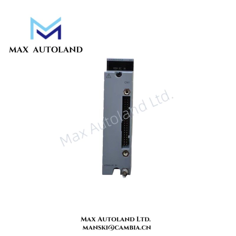
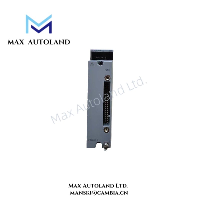
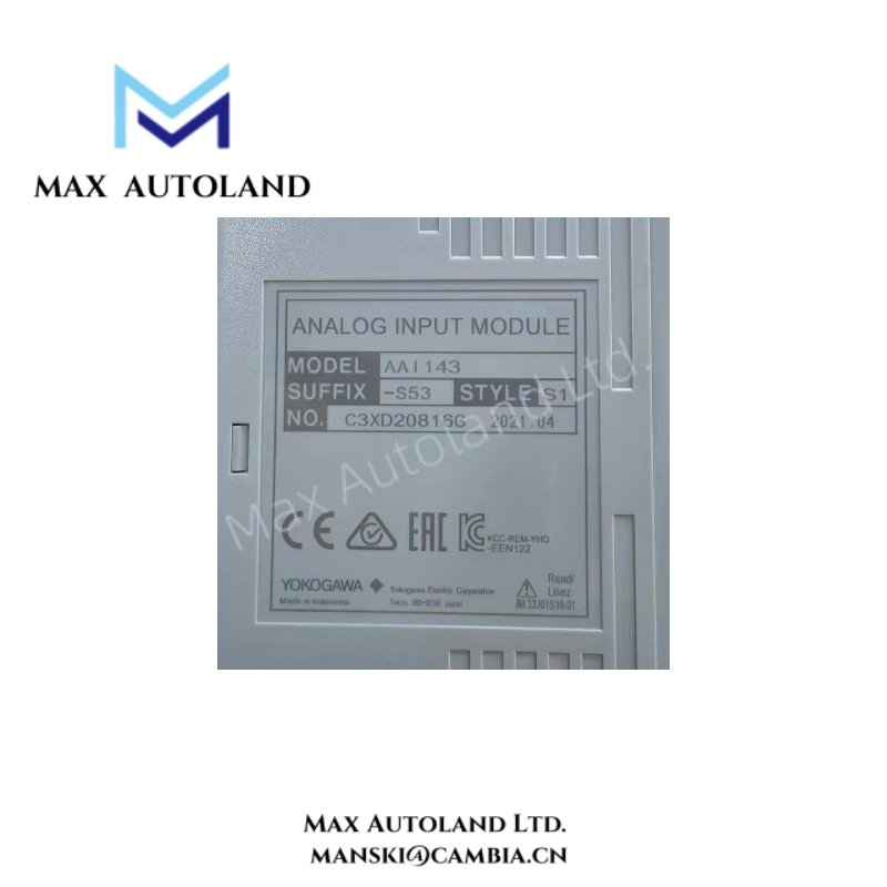
Overview
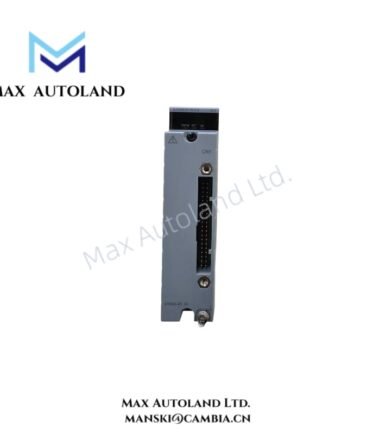
Configured for 4-20 mA signal output in Yokogawa DCS systems, the Yokogawa AAI543-S53/K4A00 (AAI543 Analog Output Module) provides 16 isolated analog output channels and supports dual-redundant operation with defined switch-over response modes.
Suffix Breakdown & Model Matrix
| Code | Specification |
|---|---|
| AAI543 | Analog Output Module, 4-20 mA, 16-channel, isolated |
| S | Standard type |
| 5 | Digital communication with HART protocol |
| 3 | ISA Standard G3 option |
| /K4A00 | KS Cable Interface Adapter for connecting AEA4D Terminal Board; adapter model ATK4A-00 |
| E | Standard switch-over response in redundant configuration with explosion protection |
| F | Fast switch-over response in redundant configuration with explosion protection |
| 0 | Basic type |
| 3 | ISA Standard G3 and temperature option, -20 to 70 deg C |
| /A4S00 | Pressure Clamp Terminal Block, model ATA4S-00 |
| /A4S10 | Pressure Clamp Terminal Block with surge absorber, model ATA4S-10 |
| /A4D00 | Dual Pressure Clamp Terminal Block, model ATA4D-00 |
| /A4D10 | Dual Pressure Clamp Terminal Block with surge absorber, model ATA4D-10 |
| /CCC01 | Connector Cover for MIL Cable, model ACCC01 |
Hardware Specifications
| Parameter | Specification |
|---|---|
| Model | AAI543-S53/K4A00 |
| Brand | Yokogawa |
| Module Type | Analog Output Module |
| Output Channels | 16 |
| Channel Configuration | Isolated |
| Output Signal | 4-20 mA |
| Redundant Configuration | Supported |
| Switch-over Response | Standard or fast response depending on suffix |
| Allowable Load Resistance | 0 to 750 ohm |
| Withstanding Voltage | 1500 VAC for 1 minute between output and system |
| Circuit-open Detection | Less than 0.65 mA |
| Accuracy | +/- 48 uA |
| Data Update Period | 10 ms |
| Temperature Drift | +/- 16 uA per 10 deg C |
| Maximum Current Consumption | 230 mA at 5 VDC; 540 mA at 24 VDC |
| Weight | Approx. 0.40 kg |
| External Connection | Pressure clamp terminal, MIL connector cable, or dedicated KS1 cable |
| HART Communication | Available |
Process Control Signal Isolation and HART Communication
The AAI543 provides 16 isolated 4-20 mA output channels for analog control signals. Channel isolation separates the output circuits from the system side and limits electrical interaction between field wiring and the DCS electronics.
Furthermore, the module supports HART communication through its specified digital communication configuration. The output circuit accepts a load resistance from 0 to 750 ohm and detects an open circuit when the output current falls below 0.65 mA.
The module updates output data every 10 ms. In redundant configurations, the specified suffix determines whether the module uses standard or fast switch-over response.
Frequently Asked Questions (FAQ)
Q: How many analog output channels does the AAI543-S53/K4A00 provide?
A: It provides 16 isolated analog output channels, with each channel supporting a 4-20 mA signal.
Q: Can the AAI543-S53/K4A00 operate in a redundant configuration?
A: Yes. The module supports dual-redundant configuration. Standard and fast switch-over response variants use different suffix codes.
Q: What load resistance can the analog outputs drive?
A: The specified allowable load resistance ranges from 0 to 750 ohm.
Field Installation Guidelines
- Install the module according to the applicable Yokogawa system hardware documentation and terminal configuration.
- Verify the exact suffix code before wiring because terminal interfaces and redundant switch-over characteristics can vary by configuration.
- Route 4-20 mA signal wiring separately from high-voltage power and high-current switching conductors where practical.
- Maintain correct polarity for each analog output loop and verify the connected field load before energizing the circuit.
- Use the specified KS cable interface, MIL connector cable, or compatible terminal assembly for the selected configuration.
- Connect cable shields according to the system grounding design and avoid creating unintended ground loops.
- Confirm that the connected load remains within the specified 0 to 750 ohm range.
- For HART applications, verify that the field loop and connected devices support the required HART communication conditions.
- During redundant installation, confirm that both module positions use compatible hardware and applicable switch-over configurations.
Emerson Top Products
| Emerson DeltaV | Epro | Ovation/Westinghouse |
| KJ1501X1-BC3 | 9100-00049-03 | 1C31122G01 |
| KJ3202X1-BA1 | A6110 | 1C31125G03 |
| KJ3222X1-BA1 | A6120 | 1C31232G01 |
| KJ3243X1-BA1 | A6125 | 1C31147G01 |
| KJ3002X1-BG1 | A6140 | 1B30035H01 |
| KJ3002X1-BB1 | A6210 | 1B30023H02 |
| KJ3001X1-BB1 | A6220 | 1B30023H01 |
| KJ3002X1-BC1 | A6312 | 1C31132G01 |
| KJ3002X1-BF1 | A6312/06 | 1C31129G03 |
| KJ3001X1-BJ1 | A6312/08 | 5X00119G01 |




Reviews
There are no reviews yet.