
Overview
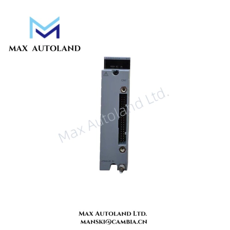
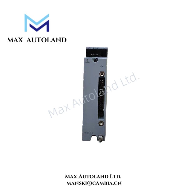
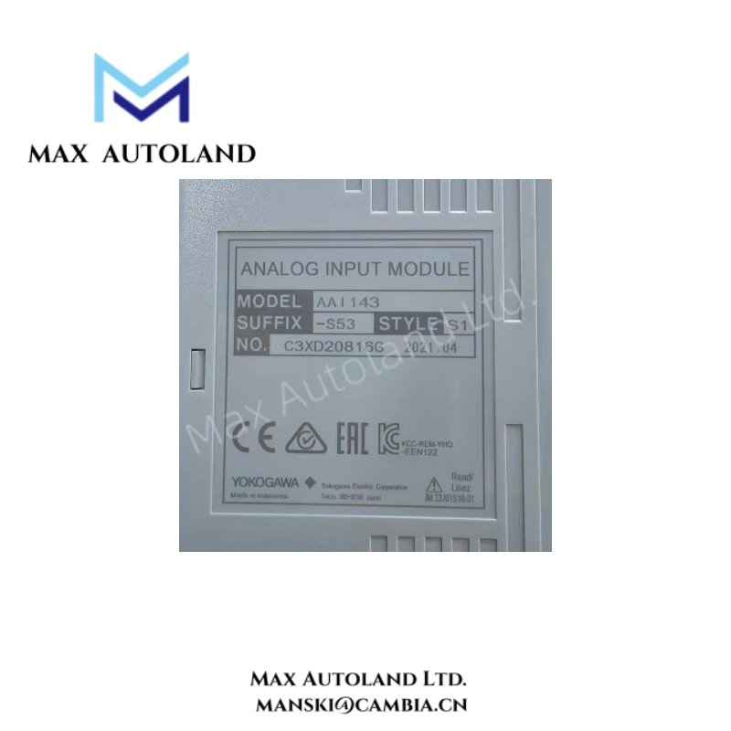
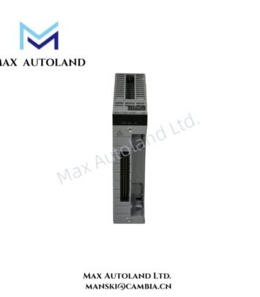
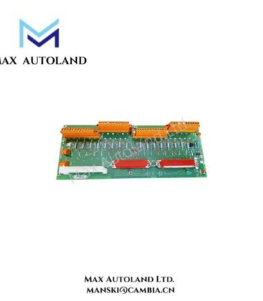
Configured for 4-20 mA DC signal acquisition in the Yokogawa CENTUM VP system, the Yokogawa AAI143-S53/K4A00 (AAI143 Analog Input Module) receives standardized current signals from 2-wire or 4-wire transmitters and supports dual-redundant configuration.
Suffix Breakdown & Model Matrix
| Code | Specification |
|---|---|
| AAI141 | Analog Input Module, 4-20 mA, 16-channel, non-isolated |
| AAI143-S00 | Earlier model designation listed in the supplied data |
| AAI143-S50 | New/updated part number listed in the supplied data |
| -H | HART digital communication option |
| -S | No explosion protection |
| -E | Explosion protection |
| 3 | ISA Standard G3 option and -20 to 70 deg C temperature option |
| /K4A00 | KS Cable Interface Adapter, Model ATK4A-00 |
| /A4S00 | Pressure Clamp Terminal Block for Analog, Model ATA4S-00 |
| /A4S10 | Pressure Clamp Terminal Block with surge absorber, Model ATA4S-10 |
| /A4D00 | Dual Pressure Clamp Terminal Block, Model ATA4D-00 |
| /A4D10 | Dual Pressure Clamp Terminal Block with surge absorber, Model ATA4D-10 |
| /CC01 | Connector Cover for MIL Cable, Model ACCC01 |
Hardware Specifications
| Parameter | Specification |
|---|---|
| Model | AAI143-S53/K4A00 |
| Base Model | AAI141 / AAI143 family |
| Brand | Yokogawa |
| System | CENTUM VP |
| Module Type | Analog Input Module |
| Number of Input Channels | 16, non-isolated |
| Input Signal | 4-20 mA DC |
| Input Configuration | 2-wire or 4-wire transmitter |
| Allowable Input Current | 27 mA |
| Input Resistance, Power ON | 400 ohm at 20 mA to 1000 ohm at 4 mA |
| Input Resistance, Power OFF | 500 kOhm or more |
| Accuracy | +/- 16 uA |
| Data Update Period | 110 ms |
| Step Response Time | 100 ms |
| Transmitter Power Supply | 14.8 VDC or more at 20 mA; 26.4 VDC or less at 0 mA |
| Transmitter Supply Current Limit | 27 mA |
| Transmitter Configuration | 2-wire or 4-wire, selected by channel pin setting |
| Ambient Temperature Drift | +/- 16 uA/10 deg C |
| Maximum Current Consumption | 310 mA at 5 VDC |
| Weight | 0.2 kg |
| Withstanding Voltage | 400 V |
| External Connection | Pressure clamp terminal, KS cable, or MIL connector cable |
| Redundant Configuration | Supported |
| Channel Isolation | Non-isolated |
| Explosion Protection | Suffix dependent |
| Mounting Interface | CENTUM VP I/O system |
Yokogawa DCS Current Loop Interface
The AAI143 family processes standardized 4-20 mA DC signals from field transmitters. Each channel accepts either a 2-wire or 4-wire transmitter connection according to the channel pin setting.
The module provides transmitter power for applicable 2-wire loops. Furthermore, the specified transmitter supply remains at 14.8 VDC or higher at 20 mA, while the maximum output current limit is 27 mA.
The supplied specification identifies the AAI141 as the 4-20 mA non-isolated reference configuration within the listed model family. Therefore, the AAI143-S53/K4A00 should be matched against the applicable Yokogawa hardware documentation before replacement or system modification.
Frequently Asked Questions (FAQ)
Q: Is the AAI143-S53/K4A00 channel-isolated?
A: No. The supplied specification identifies the 16-channel current input configuration as non-isolated.
Q: Can the module operate with both 2-wire and 4-wire transmitters?
A: Yes. The transmitter configuration uses a channel-level pin setting to select 2-wire or 4-wire operation.
Q: Does the module support redundant operation?
A: Yes. The supplied specifications state that the module can operate in a dual-redundant configuration.
Field Installation Guidelines
- Verify the CENTUM VP I/O configuration before installing the module.
- Confirm the module suffix and terminal interface before wiring.
- Configure each channel for the intended 2-wire or 4-wire transmitter arrangement.
- Route analog signal cables separately from high-voltage and high-current wiring.
- Maintain appropriate cable shielding and connect the shield according to the Yokogawa installation standard.
- Check loop polarity and transmitter supply requirements before energizing the circuit.
- Do not exceed the specified 27 mA transmitter supply current limit.
- Verify the 4-20 mA loop signal with suitable test equipment during commissioning.
- For redundant configurations, confirm both module positions and associated system configuration before applying power.
- Use the specified KS cable, pressure clamp terminal, or MIL connector interface according to the selected suffix.
Emerson Top Products
| Emerson DeltaV | Epro | Ovation/Westinghouse |
| KJ1501X1-BC3 | 9100-00049-03 | 1C31122G01 |
| KJ3202X1-BA1 | A6110 | 1C31125G03 |
| KJ3222X1-BA1 | A6120 | 1C31232G01 |
| KJ3243X1-BA1 | A6125 | 1C31147G01 |
| KJ3002X1-BG1 | A6140 | 1B30035H01 |
| KJ3002X1-BB1 | A6210 | 1B30023H02 |
| KJ3001X1-BB1 | A6220 | 1B30023H01 |
| KJ3002X1-BC1 | A6312 | 1C31132G01 |
| KJ3002X1-BF1 | A6312/06 | 1C31129G03 |
| KJ3001X1-BJ1 | A6312/08 | 5X00119G01 |




Reviews
There are no reviews yet.