
Overview
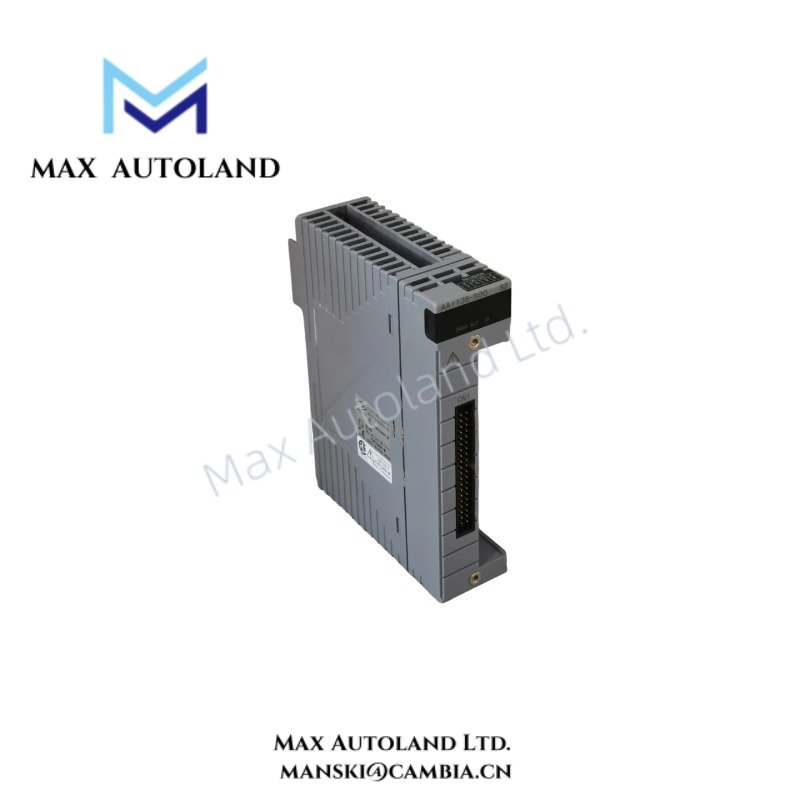
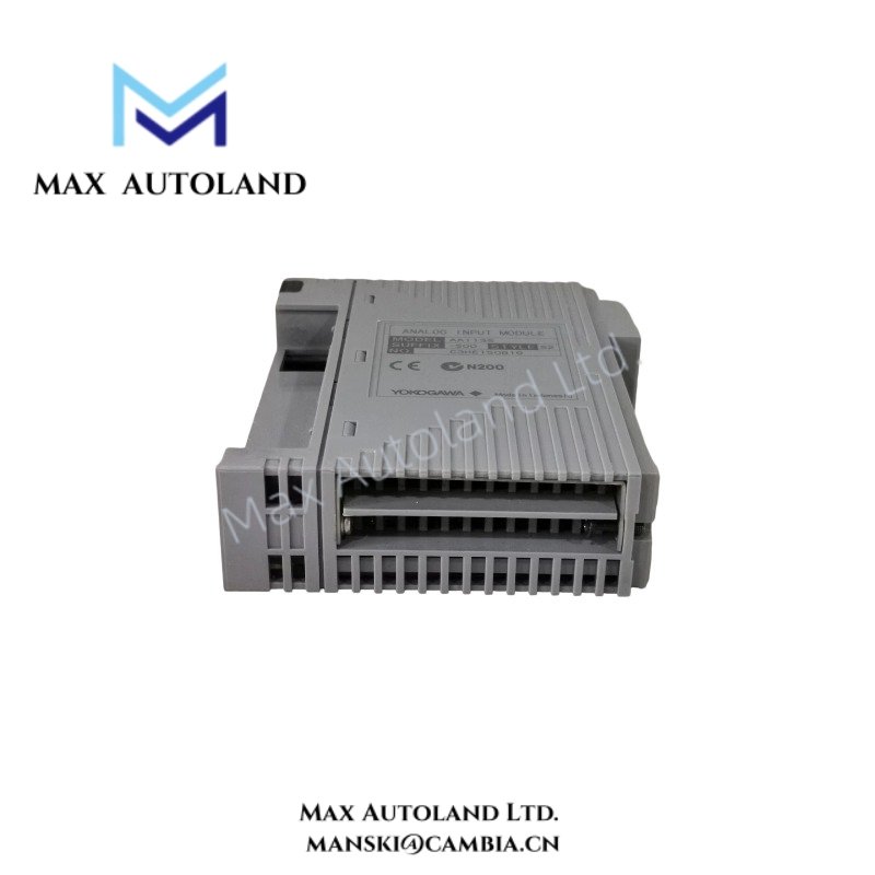
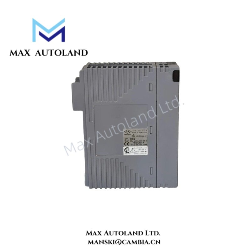
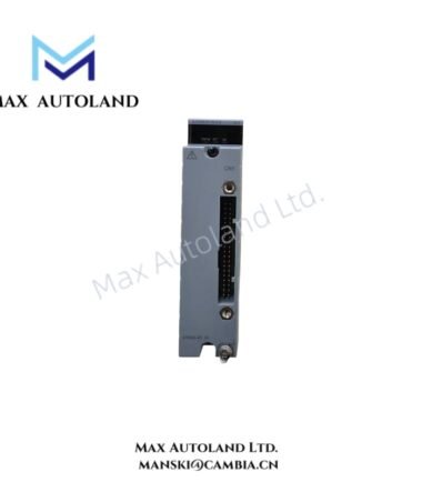
Configured for isolated 4-20 mA signal acquisition in Yokogawa DCS systems, the Yokogawa AAI135-S53 (AAI135 Analog Input Module) provides 8 isolated input channels with channel-to-channel and field-to-system isolation. The AAI135-S53 serves as the replacement for the discontinued AAI135-S03 and supports dual redundant configuration.
Suffix Breakdown & Model Matrix
| Code | Specification |
|---|---|
| AAI135 | Analog Input Module, 4-20 mA, 8-channel, isolated |
| S | Standard type |
| H | Digital communication with HART protocol |
| 5 | No explosion protection |
| E | Explosion protection |
| 0 | Basic type |
| 3 | ISA Standard G3 option and -20 to 70 deg C temperature option |
| /13A00 | KS Cable Interface Adapter, ATI3A-00 |
| /K4A00 | KS Cable Interface Adapter, ATK4A-00 |
| /13S00 | Pressure Clamp Terminal Block for Isolated Analog, ATI3S-00 |
| /13S10 | Pressure Clamp Terminal Block with surge absorber, ATI3S-10 |
| /13D00 | Dual Pressure Clamp Terminal Block for Isolated Analog, ATI3D-00 |
| /13D10 | Dual Pressure Clamp Terminal Block with surge absorber, ATI3D-10 |
| /CCC01 | Connector Cover for MIL Cable, ACCC01 |
The supplied documentation identifies AAI135-S53 as the replacement model for discontinued AAI135-S03. The source data does not define a separate suffix-code decomposition for the exact S53 replacement designation, so no additional interpretation is applied.
Hardware Specifications
| Parameter | Specification |
|---|---|
| Model | AAI135-S53 |
| Replacement For | AAI135-S03 |
| Brand | Yokogawa |
| Module Type | Analog Input Module |
| Input Channels | 8 |
| Input Signal | 4-20 mA DC |
| Channel Configuration | Isolated channels |
| Field-to-System Isolation | 500 V AC for 1 minute |
| Channel-to-Channel Isolation | 500 V AC for 1 minute |
| Allowable Input Current | 25 mA |
| Input Resistance, Power ON | 290 ohm at 20 mA to 450 ohm at 4 mA |
| Input Resistance, Power OFF | 500 kohm or more |
| Allowable Load Resistance | 0 to 750 ohm |
| Circuit-Open Detection | Less than 10.65 mA |
| Accuracy | +/-16 uA |
| Data Update Period | 10 ms |
| Transmitter Power Supply | 15.0 VDC or more at 20 mA; 29.3 VDC or less at 0 mA |
| Temperature Drift | +/-16 uA/10 deg C |
| Maximum Current Consumption | 360 mA at 5 VDC; 450 mA at 24 VDC |
| Weight | 0.3 kg |
| Dimensions | Not specified in supplied data |
| Operating Temp | -20 to 70 deg C when the specified temperature option applies |
| External Connection | Pressure clamp terminal, MIL connector cable, dedicated KS1 cable |
| HART Communication | Available with applicable HART configuration |
| Redundant Configuration | Dual redundant configuration supported |
Yokogawa DCS Signal Isolation and HART Interface
The AAI135 architecture isolates the field circuits from the system circuits. In addition, each input channel maintains isolation from the other input channels. Therefore, field-side signal differences do not directly propagate between individual input channels.
The module accepts standard 4-20 mA current signals and updates input data every 10 ms. Where the applicable HART configuration is selected, the module also supports digital HART communication over the analog current loop.
The transmitter supply provides at least 15.0 VDC at 20 mA while maintaining a maximum specified output of 29.3 VDC at 0 mA. Meanwhile, the module permits dual redundant configuration for systems requiring redundant I/O operation.
Frequently Asked Questions (FAQ)
Q: What signal does the AAI135-S53 accept?
A: The module accepts 4-20 mA DC analog input signals across 8 isolated input channels.
Q: Does the AAI135-S53 isolate individual input channels?
A: Yes. The supplied specifications define 500 V AC isolation for 1 minute between input channels and between the input circuits and system.
Q: Can the AAI135-S53 operate in a redundant configuration?
A: Yes. The module supports dual redundant configuration. The supplied data does not specify a numerical redundancy switching delay.
Field Installation Guidelines
- Confirm the installed module designation before wiring. The supplied documentation identifies AAI135-S53 as the replacement for discontinued AAI135-S03.
- Verify that the connected transmitter provides a compatible 4-20 mA current signal.
- Keep analog signal wiring separated from high-voltage and high-current conductors to reduce induced interference.
- Maintain the specified polarity of each current loop during field termination.
- Use the specified pressure clamp terminal, MIL connector cable, or dedicated KS1 cable according to the selected external connection arrangement.
- Route shielded analog cables according to the site’s instrumentation grounding standard. Avoid creating unintended ground loops through multiple shield termination points.
- Verify the transmitter loop resistance against the specified allowable load resistance of 0 to 750 ohm.
- Before energizing the loop, inspect terminal tightness, cable identification, polarity, and insulation condition.
- For redundant installations, verify the DCS configuration and physical module arrangement before placing the redundant pair into service.
- Where HART communication is configured, verify that the loop wiring and connected field device support the required HART communication path.
Emerson Top Products
| Emerson DeltaV | Epro | Ovation/Westinghouse |
| KJ1501X1-BC3 | 9100-00049-03 | 1C31122G01 |
| KJ3202X1-BA1 | A6110 | 1C31125G03 |
| KJ3222X1-BA1 | A6120 | 1C31232G01 |
| KJ3243X1-BA1 | A6125 | 1C31147G01 |
| KJ3002X1-BG1 | A6140 | 1B30035H01 |
| KJ3002X1-BB1 | A6210 | 1B30023H02 |
| KJ3001X1-BB1 | A6220 | 1B30023H01 |
| KJ3002X1-BC1 | A6312 | 1C31132G01 |
| KJ3002X1-BF1 | A6312/06 | 1C31129G03 |
| KJ3001X1-BJ1 | A6312/08 | 5X00119G01 |




Reviews
There are no reviews yet.