
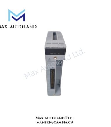
Overview
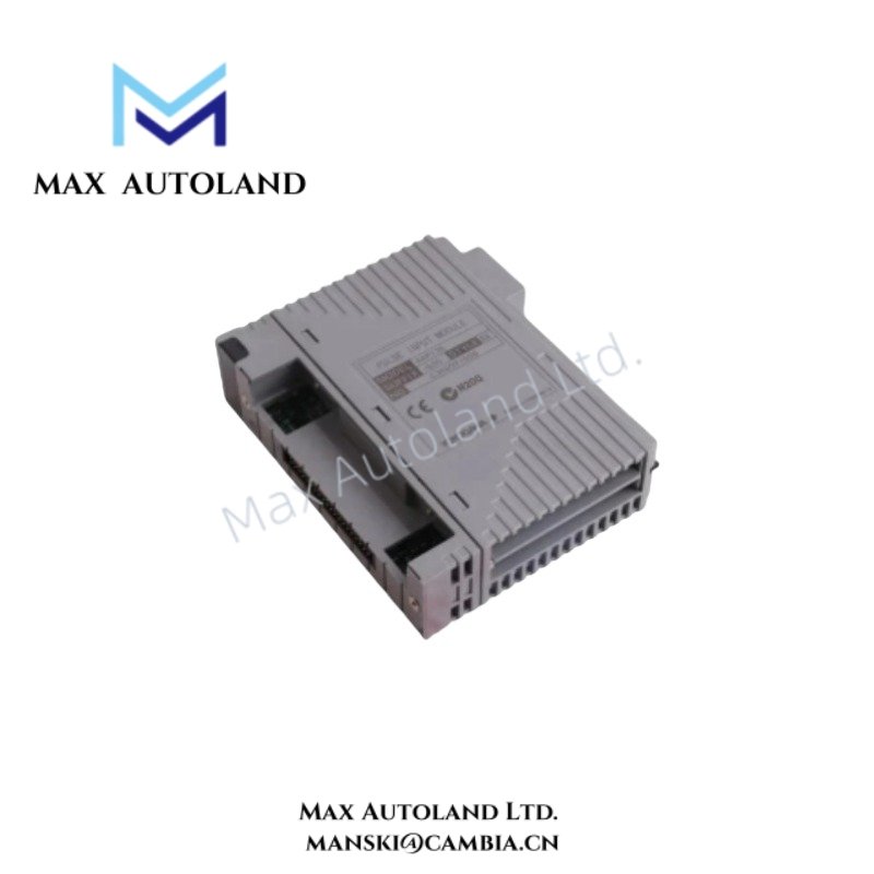
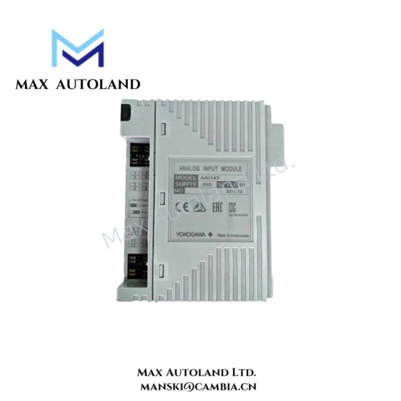
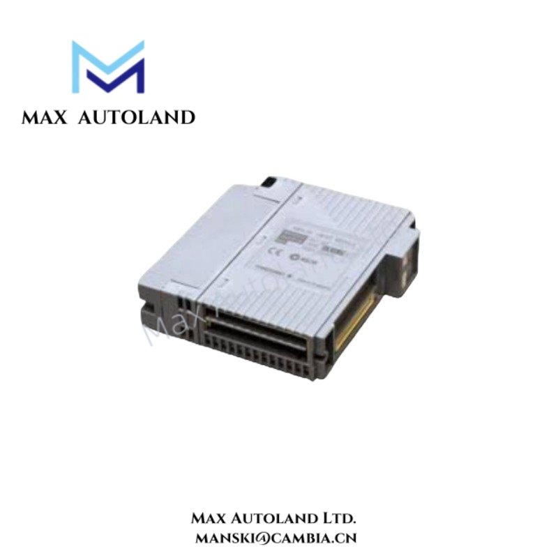
Configured for isolated 4-20 mA signal acquisition in Yokogawa DCS platforms, the Yokogawa AAI143-S50/A4S10 (AAI143 Analog Input Module) provides direct electrical input processing for 16 field channels. The module supports HART communication, selectable 2-wire or 4-wire transmitter connections, and channel-to-system isolation.
Suffix Breakdown & Model Matrix
| Code | Specification |
|---|---|
| AAI143 | 16-channel isolated analog input module |
| -S50 | Standard basic type without explosion protection |
| /A4S10 | Supplied with ATA4S-10 pressure clamp terminal block with built-in surge absorber |
| Complete Model | AAI143-S50/A4S10 |
Hardware Specifications
| Parameter | Specification |
|---|---|
| Model | AAI143-S50/A4S10 |
| Brand | Yokogawa |
| Module Type | Analog Input Module |
| Origin | Not specified in supplied data |
| Weight | Approx. 0.3 kg, excluding terminal block |
| Dimensions | Not specified in supplied data |
| Operating Temp | Not specified in supplied data |
| Power Consumption | Max. 230 mA at 5 VDC; max. 540 mA at 24 VDC |
| Number of Channels | 16 |
| Channel Configuration | Fully isolated |
| Input Signal | 4-20 mA DC |
| Allowable Input Current | Up to 24 mA |
| Measurement Accuracy | +/- 16 uA |
| Data Update Period | 10 ms |
| Input Resistance, Power ON | 270 ohm at 20 mA to 350 ohm at 4 mA |
| Input Resistance, Power OFF | 500 kohm or larger |
| Transmitter Supply Voltage | 19.0 V or higher at 20 mA; 25.5 V or less at 0 mA |
| Transmitter Current Limit | 25 mA |
| Transmitter Connection | Selectable 2-wire or 4-wire per channel |
| Digital Communication | HART protocol |
| Withstanding Voltage | 1,500 VAC between input and system for 1 minute |
| Temperature Drift | +/- 16 uA per 10 deg C change |
| Redundancy | Dual-redundant configuration supported |
| Terminal Block | ATA4S-10 pressure clamp terminal block |
| Surge Protection | Built-in surge absorber in ATA4S-10 |
| Explosion Protection | None |
4-20 mA HART and Channel Isolation
The AAI143 processes standard 4-20 mA transmitter signals while maintaining electrical isolation between field input channels and the system interface. Therefore, each channel can acquire process current independently within the specified input range.
The module supports HART communication over compatible 4-20 mA loops. This allows digital device information to accompany the analog process variable without replacing the standard current signal. Consequently, connected field devices can provide digital diagnostic or configuration information through the same loop.
The transmitter interface supports both 2-wire and 4-wire configurations through channel-specific pin settings. In addition, the module provides a 19.0 V or higher transmitter supply at 20 mA, with a 25 mA current limit.
The input circuit accepts up to 24 mA. Furthermore, the specified measurement accuracy is +/- 16 uA, while the data update period is 10 ms. The input-to-system withstand voltage reaches 1,500 VAC for 1 minute.
Frequently Asked Questions (FAQ)
Q: Does the AAI143-S50/A4S10 support HART communication?
A: Yes. The module supports HART communication over compatible 4-20 mA input loops.
Q: Can the module connect to both 2-wire and 4-wire transmitters?
A: Yes. Each channel can be configured for either 2-wire or 4-wire transmitter connection through the specified pin setting.
Q: What terminal block does the AAI143-S50/A4S10 include?
A: The supplied configuration includes an ATA4S-10 pressure clamp terminal block with a built-in surge absorber.
Field Installation Guidelines
- Install the module and terminal block according to the applicable Yokogawa system hardware documentation.
- Verify the module model and terminal block configuration before wiring field transmitters.
- Configure each channel for the required 2-wire or 4-wire transmitter arrangement before applying field power.
- Route low-level 4-20 mA and HART signal wiring separately from high-voltage power and high-current switching conductors where practical.
- Maintain correct polarity on current input and transmitter supply connections.
- Connect cable shields according to the Yokogawa DCS grounding and shielding scheme used by the installation.
- Verify the transmitter supply voltage and current requirements before connecting the field device.
- Inspect the ATA4S-10 surge absorber and terminal connections during commissioning if the installation requires transient protection.
- Confirm channel isolation and signal continuity before placing the loop into process service.
- Do not exceed the specified 24 mA input current or 25 mA transmitter supply current limit.
Emerson Top Products
| Emerson DeltaV | Epro | Ovation/Westinghouse |
| KJ1501X1-BC3 | 9100-00049-03 | 1C31122G01 |
| KJ3202X1-BA1 | A6110 | 1C31125G03 |
| KJ3222X1-BA1 | A6120 | 1C31232G01 |
| KJ3243X1-BA1 | A6125 | 1C31147G01 |
| KJ3002X1-BG1 | A6140 | 1B30035H01 |
| KJ3002X1-BB1 | A6210 | 1B30023H02 |
| KJ3001X1-BB1 | A6220 | 1B30023H01 |
| KJ3002X1-BC1 | A6312 | 1C31132G01 |
| KJ3002X1-BF1 | A6312/06 | 1C31129G03 |
| KJ3001X1-BJ1 | A6312/08 | 5X00119G01 |








Reviews
There are no reviews yet.