Overview
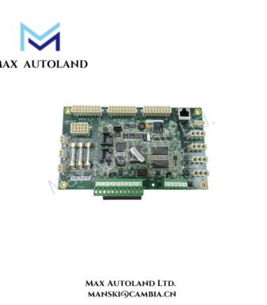
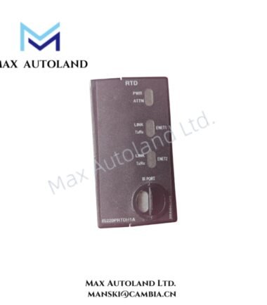
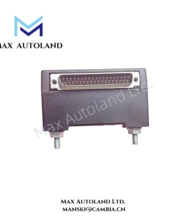
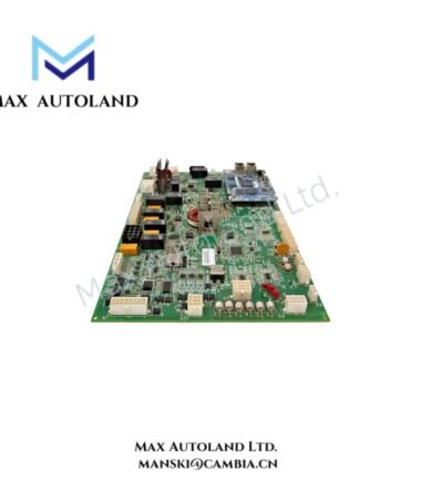
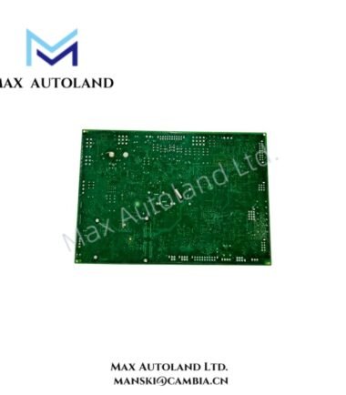
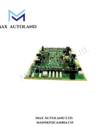
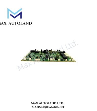
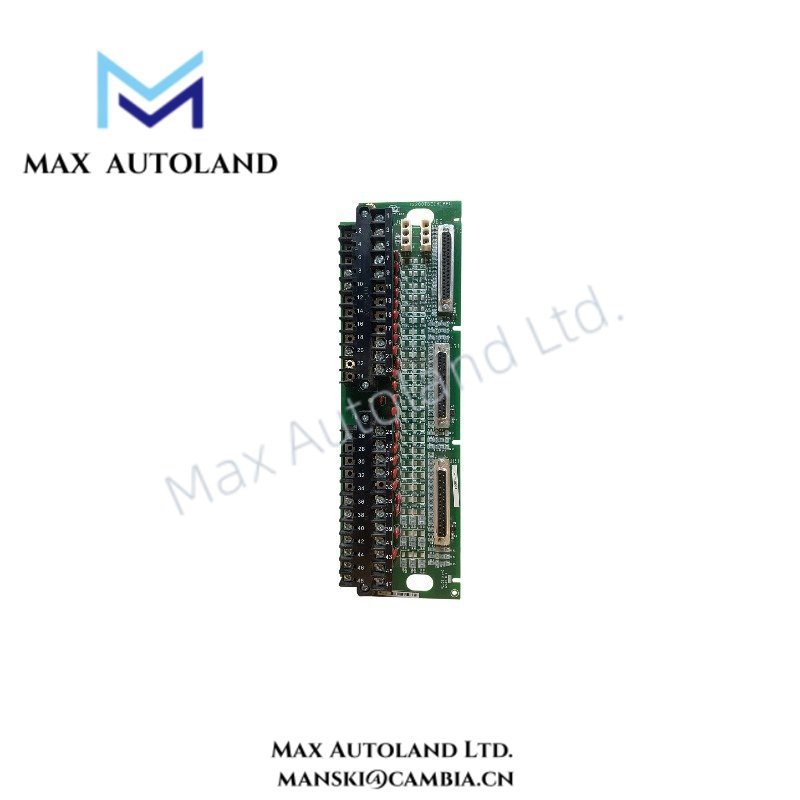
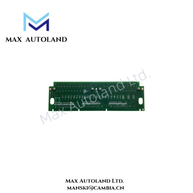
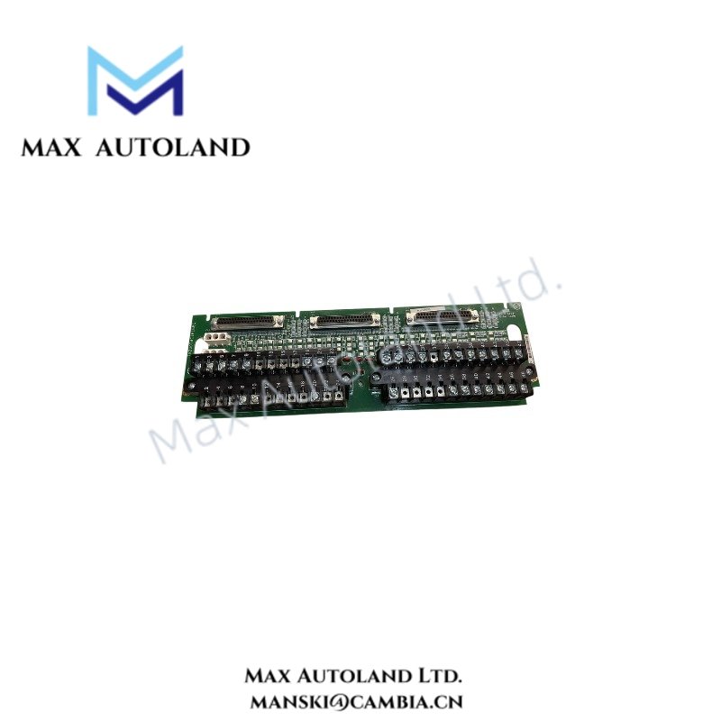
Configured for 16-channel dry contact signal acquisition, the GE IS200TBCIH1BBC (IS200TBCIH1B Contact Input Terminal Board) provides direct electrical termination for 24 VDC digital contact inputs within GE control hardware.
Hardware Specifications
| Parameter | Specification |
|---|---|
| Model | IS200TBCIH1BBC |
| Spare Model | IS200TBCIH1B |
| Brand | General Electric (GE) |
| Product Type | Contact Input Terminal Board |
| Origin | USA |
| Weight | 0.54 kg |
| Power Consumption | Typically 150 mA |
| Input Channels | 16 digital contact input channels |
| Input Type | Dry contact inputs |
| Nominal Supply Voltage | 24 VDC |
| Maximum Supply Voltage | 30 VDC |
| Active Channel Current | 4-8 mA per channel |
GE Industrial I/O Characteristics
The IS200TBCIH1BBC accepts discrete contact states through 16 input channels. Each channel uses a dry contact input arrangement and operates from a nominal 24 VDC supply.
Furthermore, an active channel draws approximately 4-8 mA. The board specifies a maximum supply voltage of 30 VDC, while typical overall current consumption is 150 mA.
The terminal board provides physical signal termination between field contact circuits and the associated GE control hardware. Therefore, installation should maintain correct channel identification, supply polarity, and field wiring separation.
The board supports high I/O density through its 16-channel digital input arrangement. However, the supplied data does not identify a specific Profinet, EtherNet/IP, or other network protocol, so no protocol-specific communication capability should be assigned to this terminal board.
Frequently Asked Questions
Q: How many digital contact input channels does the IS200TBCIH1BBC provide?
A: The board provides 16 digital contact input channels.
Q: What input signal type does the IS200TBCIH1BBC use?
A: It uses dry contact inputs with a nominal 24 VDC supply and approximately 4-8 mA per active channel.
Q: What is the specified maximum supply voltage?
A: The maximum specified supply voltage is 30 VDC.
Field Installation Guidelines
- Verify the complete part number before installation and confirm that the terminal board matches the intended GE control hardware configuration.
- De-energize the associated field circuit before terminating or removing wiring.
- Confirm the 24 VDC nominal supply before connecting field contact circuits.
- Do not exceed the specified 30 VDC maximum supply voltage.
- Keep contact input wiring separated from high-current and high-voltage conductors to reduce electrical interference.
- Identify each of the 16 input channels according to the system wiring documentation before commissioning.
- Inspect terminal connections for secure mechanical engagement and correct conductor placement.
- Use appropriate field grounding and shielding practices according to the cabinet and control-system installation standard.
- After wiring, verify each contact input independently before placing the associated control logic into service.