
Overview
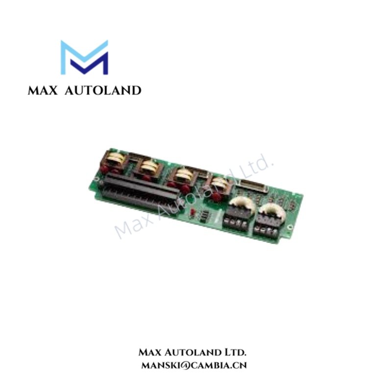
Configured for generator PT voltage and CT current signal reception, isolation, and measurement-level routing in the GE EX2100 Excitation Control System, the GE IS200EPCTG2AZZ (IS200EPCTG2A Exciter PT/CT Terminal Board) provides direct electrical signal conditioning between field transformers and controller I/O circuitry.
Suffix Breakdown & Model Matrix
| Parameter | Specification |
|---|---|
| Full Model | IS200EPCTG2AZZ |
| Base Model | IS200EPCTG2A |
| Functional Acronym | EPCT |
| Model Type | Exciter PT/CT Terminal Board |
| Suffix Information | ZZ is identified in the supplied data as a factory-assembled hardware revision variant |
| System | EX2100 Excitation Control System |
Hardware Specifications
| Parameter | Specification |
|---|---|
| Model | IS200EPCTG2AZZ |
| Brand | General Electric (GE) |
| Series | EX2100 Excitation Control System |
| Product Type | Exciter PT/CT Terminal Board |
| Weight | Approximately 0.45 kg |
| Dimensions | Approximately 23.8 cm H x 8.6 cm W |
| Operating Temp | -30 to 65 deg C |
| Power Consumption | Not specified in supplied data |
| PT Voltage Inputs | 115 Vrms, 50/60 Hz, multi-phase |
| CT Inputs | 1 A or 5 A |
| Additional Analog Input | Configurable voltage or 4-20 mA current input |
| Isolation Transformers | T1 through T6 |
| Diagnostic Test Points | TP1 through TP8 |
| Board Protection | Industrial conformal coating |
Generator PT/CT Signal Isolation and Scaling
The IS200EPCTG2AZZ receives generator potential transformer and current transformer signals from the field. The onboard transformer network uses isolation transformers T1 through T6 to separate the incoming measurement circuits from downstream control electronics.
The PT inputs accept multi-phase signals rated at 115 Vrms and 50/60 Hz. In addition, the CT interface accepts standard 1 A or 5 A secondary current signals. The board also provides a non-isolated analog input that can accept a voltage signal or a 4-20 mA current signal.
The TP1 through TP8 test points provide access to transformer secondary-side signals for electrical verification. Therefore, technicians can inspect the conditioned signal paths without directly accessing the incoming transformer circuits.
Frequently Asked Questions
Q: What PT signal level does the IS200EPCTG2AZZ support?
A: The supplied data specifies multi-phase generator PT inputs rated at 115 Vrms and 50/60 Hz.
Q: What CT input levels does the board accept?
A: The specified CT inputs support standard 1 A or 5 A levels.
Q: Does the board provide signal isolation?
A: Yes. The supplied data identifies six onboard isolation transformers, designated T1 through T6.
Field Installation Guidelines
Install the board in the designated EX2100 cabinet position and secure all mechanical mounting points before connecting field wiring.
Verify PT and CT circuit identification before termination. Keep PT and CT conductors clearly separated from unrelated control and power wiring where the cabinet layout permits. Maintain correct polarity and phase identification throughout the transformer secondary circuits.
For the 4-20 mA input, verify the selected signal type and terminal assignment before energization. Do not connect an external signal to an unverified terminal.
Use the TP1 through TP8 test points for controlled electrical inspection according to the applicable GE documentation. Keep test equipment connections secure and avoid accidental contact between adjacent test points.
Route cable shields according to the site grounding scheme. Avoid using signal shields as unintended current-carrying conductors. Before commissioning, verify terminal continuity, PT/CT wiring, input polarity, grounding, and isolation against the applicable EX2100 wiring documentation.


