



Overview
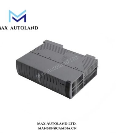
Configured for excitation contact input monitoring and relay contact output routing in the GE EX2100 Excitation Control System, the GE IS200ECTBG3A (ECTB Exciter Contact Terminal Board) provides direct physical and electrical interfacing between field contacts and controller circuitry.
Hardware Specifications
| Parameter | Specification |
|---|---|
| Model | IS200ECTBG3A |
| Base Model | ECTB |
| Brand | General Electric (GE) / GE Industrial Systems |
| Series | EX2100 Excitation Control System |
| Product Type | Exciter Contact Terminal Board |
| Relay Outputs | 2 trip contact outputs; 4 general-purpose Form-C relay outputs |
| Relay Control Voltage | 24 VDC |
| Contact Inputs | Multiple auxiliary contact inputs |
| Dedicated Monitoring Inputs | 52G and 86G contacts |
| Contact Wetting Voltage | Nominal 70 VDC |
| Dimensions | Approximately 150 mm x 76 mm x 90 mm |
| Weight | Approximately 0.34 kg |
| Operating Temp | Standard industrial temperature range; exact range not specified |
| Power Consumption | Not specified in supplied data |
| Mounting | Internal cabinet mounting within EX2100 enclosures |
| Environmental Protection | Conformal coating |
EX2100 Contact and Relay Interface
The ECTB board processes discrete excitation-system signals through dedicated contact input and relay output circuits. Auxiliary contacts receive a nominal 70 VDC wetting voltage for contact monitoring. The board also provides dedicated monitoring paths for 52G and 86G system contacts.
The output section provides two trip contact outputs and four Form-C relay outputs. Each Form-C output provides Normally Open, Normally Closed, and Common terminals. The controller drives the relay interface at 24 VDC.
Frequently Asked Questions
Q: What relay outputs does the IS200ECTBG3A provide?
A: It provides 2 trip contact outputs and 4 general-purpose Form-C relay contact outputs.
Q: What voltage does the board use for contact wetting?
A: The supplied technical data specifies a nominal 70 VDC contact wetting voltage.
Q: What controller-side voltage controls the relay interface?
A: The supplied data specifies 24 VDC for relay control.
Field Installation Guidelines
Install the IS200ECTBG3A inside the designated EX2100 cabinet location and secure the board against mechanical movement. Before wiring, verify the board identification and terminal assignments against the applicable GE documentation.
Route discrete contact wiring separately from high-current power conductors where the cabinet design permits. Maintain clear terminal identification for the 52G, 86G, auxiliary contact, and relay circuits.
Connect cable shields and cabinet protective conductors according to the site grounding design. Avoid creating unintended ground loops through signal wiring. Before energization, verify terminal polarity, contact continuity, relay wiring, and the specified contact-wetting circuit.
Do not apply field voltage to an unverified terminal. Confirm the installed board revision and system wiring against the applicable EX2100 configuration before commissioning.