

Overview
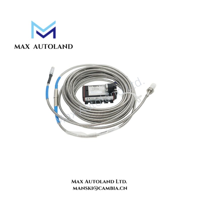
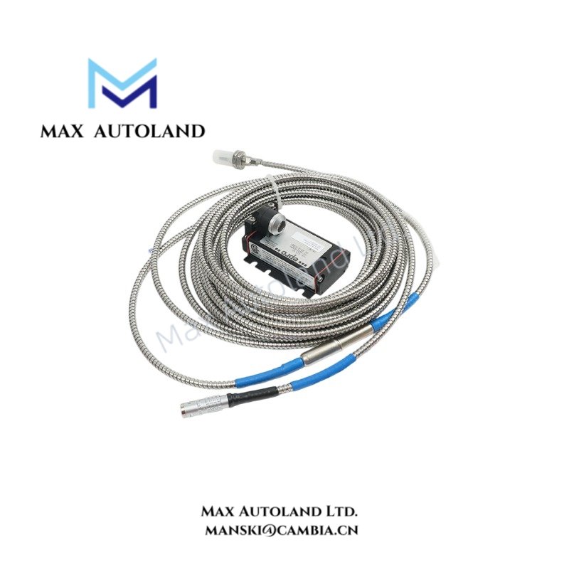
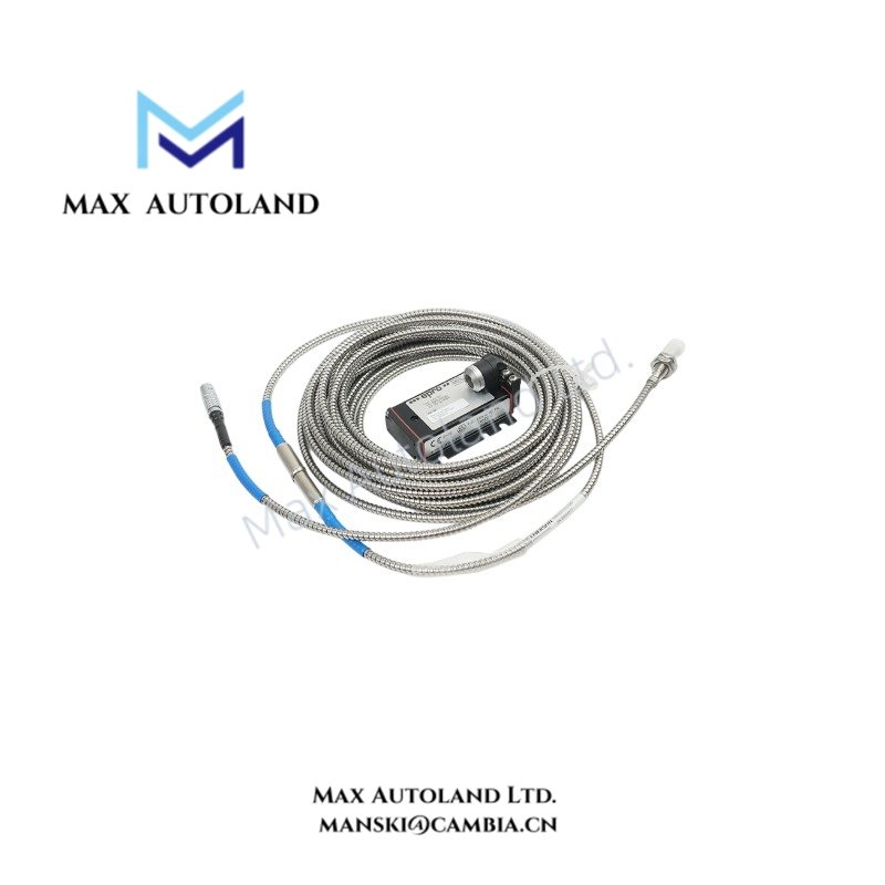
Configured for radial and axial shaft vibration acquisition in machinery monitoring systems, the Emerson PR6423/010-040 (PR6423/010-040 8 mm Eddy Current Proximity Sensor) provides direct physical signal execution by transforming air gap displacement into proportional electrical voltage.
Hardware Specifications
| Parameter | Specification |
|---|---|
| Model | PR6423/010-040 |
| Brand | Emerson / Epro |
| Origin | Germany / Global Manufacturing Facility |
| Weight | Approximately 0.45 kg (including cable) |
| Dimensions | Sensor Tip Diameter: 8 mm; Case Thread: 3/8″-24 UNF; Cable Length: 10.0 meters |
| Operating Temp | Sensor head: -35 deg C to +200 deg C; Extension cable & connector: -35 deg C to +150 deg C |
| Power Consumption | Powered via compatible signal converter (e.g., CON021 / CON041 series) |
| Linear Measurement Range | 2 mm (80 mils) |
| Incremental Scale Factor | 8 V/mm (203.2 mV/mil) ± 5% |
| Frequency Response | 0 to 20 kHz (-3 dB) |
4-20 mA HART Loop Protocol and Signal Conditioning
As part of process control and DCS instrumentation ecosystems, the PR6423 series interfaces directly with signal converters to translate non-contact eddy current gap variations into standardized signals. Channel-to-channel isolation within the monitoring hardware prevents ground loops and electrical noise propagation across extensive industrial instrumentation architectures. Furthermore, the signal conditioning chain ensures stable static position tracking and dynamic vibration output without introducing phase distortion across the 0 to 20 kHz frequency response bandwidth.
Frequently Asked Questions
Q: What is the recommended initial static air gap setting for the PR6423/010-040 sensor?
A: The probe is typically centered around an initial air gap of 0.5 mm (20 mils) to maintain operation within its 2 mm linear measurement range.
Q: Can the 10.0-meter integral armored cable be shortened in the field?
A: No. Altering the integral cable length changes the electrical capacitance of the resonant circuit, which directly degrades the calibrated Incremental Scale Factor (ISF) of 8 V/mm.
Field Installation Guidelines
When mounting the 3/8″-24 UNF threaded probe body into machinery housings, operators must secure the sensor using double locknuts to prevent mechanical loosening caused by continuous operational vibration. The sensor tip requires a clear, unobstructed target area of conductive ferromagnetic steel—such as standard 42CrMo4 or AISI 4140 shafts—with a diameter at least twice the probe tip size to ensure accurate readings. Route the 10.0-meter coaxial cable away from high-voltage power conduits and variable frequency drive (VFD) motor leads to minimize electromagnetic interference, and ensure proper shield grounding exclusively at the control cabinet side to avoid ground loop current injection.


Reviews
There are no reviews yet.