
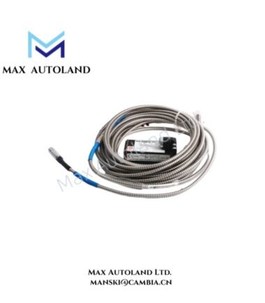
Overview
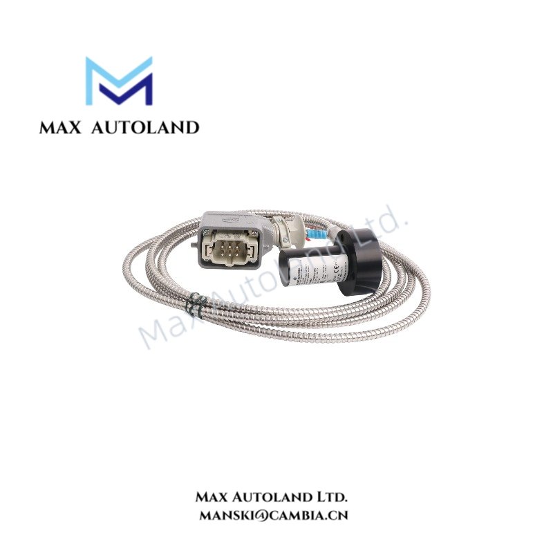
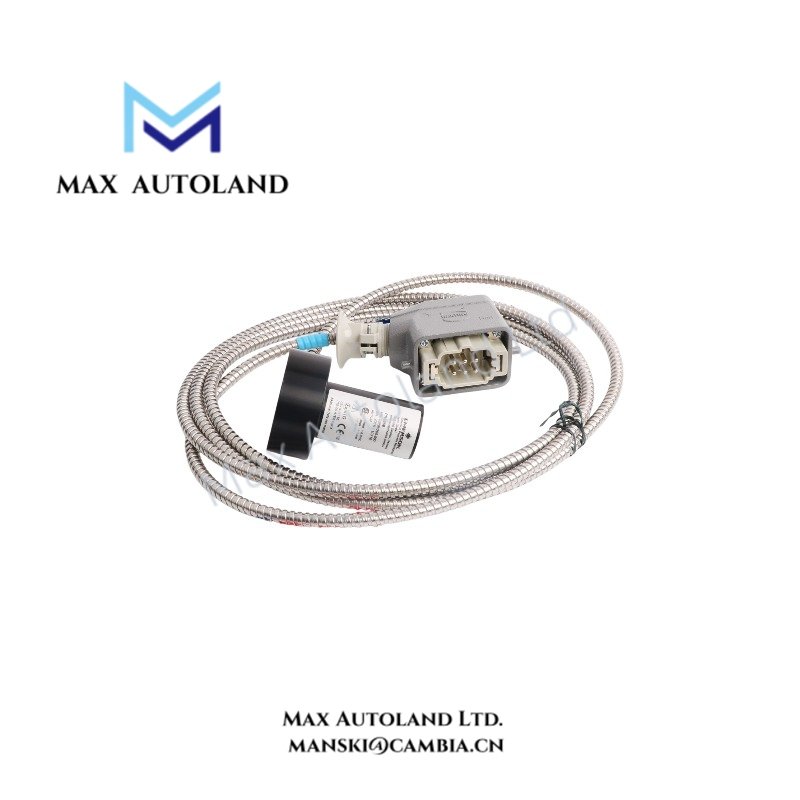
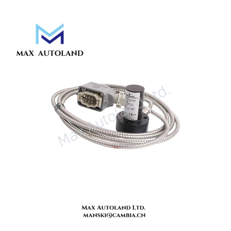
Emerson EPRO PR9268/20 Electrodynamic Velocity Sensor Series
The Emerson EPRO PR9268/20, also cataloged as the PR9268/20 Electrodynamic Velocity Sensor, operates as a dedicated hardware component for absolute bearing housing vibration measurement within industrial turbine monitoring networks.
Hardware Specifications
| Parameter | Specification |
|---|---|
| Model | PR9268/20 |
| Brand | Emerson / EPRO |
| Origin | Germany |
| Weight | Approx. 930 g to 960 g (variant dependent) |
| Dimensions | Standard industrial cylindrical housing |
| Operating Temp | -20 deg C to +100 deg C |
| Power Consumption | Self-powered (0 W external supply required) |
| Measurement Principle | Electrodynamic (self-powered moving coil) |
| Sensitivity | Typically 28.5 mV/mm/s (723.9 mV/in/s) |
| Frequency Range | 4 to 1000 Hz |
| Natural Frequency | 4.5 Hz +/- 0.75 Hz (at +20 deg C) |
| Amplitude Linearity | < 2% |
| Max Acceleration Limit | 10 g (98.1 m/s^2) peak-peak continuous |
| Coil Electrical Resistance | 1875 Ohm +/- 10% |
| Protection Class | IP55 |
| Housing Material | Al-Mg-Si alloy |
Channel-to-Channel Isolation and Signal Transmission
The module architecture enforces strict channel separation and balanced-to-ground signal pathways to suppress electromagnetic interference (EMI) and radio frequency interference (RFI) across industrial cabinets. Because the moving-coil mechanism generates an internal electromagnetic induction current, the device directly outputs an analog AC voltage signal proportional to physical velocity, bypassing active loop power requirements while maintaining robust signal fidelity.
Frequently Asked Questions
Q: Does the PR9268/20 require an external power supply loop?
A: No, the sensor is entirely self-powered via its internal moving-coil electromagnetic induction mechanism, generating its own output voltage signal directly from mechanical kinetic energy.
Q: What is the maximum continuous acceleration limit for this sensor?
A: The sensor sustains a maximum continuous acceleration of 10 g (98.1 m/s^2) peak-peak, with an intermittent operational limit of up to 20 g.
Field Installation Guidelines
Ensure the designated mounting surface is flat, clean, and mechanically rigid to prevent structural resonance distortion. Torque the mounting threads according to standard mechanical protocols while respecting the specified orientation limits for horizontal or vertical variants. Route all signal cables away from high-voltage power conduits, and terminate the cable shield securely at the monitoring rack grounding bar to minimize common-mode noise injection.


Reviews
There are no reviews yet.