
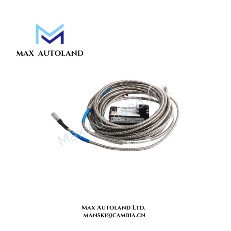
Overview
Configured for non-contact displacement and vibration measurement, the Emerson EPRO PR9266-12 (PR9266-12 Eddy Current Sensor) provides an analog 4-20 mA output for machinery monitoring circuits. The sensor measures the position of a conductive target without mechanical contact. Its stated operating range is 0.5 mm to 100 mm, depending on the application and setup.
Hardware Specifications
| Parameter | Specification |
|---|---|
| Model | PR9266-12 |
| Brand | Emerson EPRO |
| Product Type | Eddy Current Sensor |
| Measuring Range | 0.5 mm to 100 mm, depending on application and setup |
| Accuracy | +/- 0.1% |
| Repeatability | +/- 0.05% |
| Output Signal | 4-20 mA |
| Power Supply | 24 VDC |
| Operating Temp | -40 deg C to +85 deg C |
| Measurement Principle | Eddy current, non-contact measurement |
Analog Current-Loop Measurement
The PR9266-12 uses a non-contact electromagnetic measurement principle to detect changes in the position of a conductive target. The sensor converts the measured condition into a 4-20 mA analog signal for connection to a compatible monitoring or control input.
The supplied specifications state a 24 VDC power supply and a measuring range of 0.5 mm to 100 mm. The actual usable range depends on the target, mechanical arrangement, and application setup.
Frequently Asked Questions
Q: Does the PR9266-12 require physical contact with the measured target?
A: No. The specified measurement principle is non-contact eddy current sensing.
Q: What signal does the PR9266-12 provide to the control or monitoring system?
A: The specified output is a 4-20 mA analog signal.
Q: What operating temperature range is specified for the sensor?
A: The supplied specification states -40 deg C to +85 deg C.
Field Installation Guidelines
- Install the sensor with a mechanically stable mounting arrangement and maintain the required target geometry specified by the application documentation.
- Keep the sensing path free from unintended conductive objects that could affect the measurement field.
- Route the 4-20 mA signal wiring separately from high-current power conductors where practical.
- Use suitable shielded instrumentation cable when the installation environment contains significant electrical interference.
- Apply the cable shield according to the site grounding scheme and the associated monitoring-system wiring requirements.
- Verify the 24 VDC supply before connecting the sensor.
- Confirm signal polarity and loop wiring before energizing the circuit.
- After installation, verify the measured output across the intended operating range and check for abnormal signal variation.
- Do not assign a specific mounting distance, target material, or calibration value unless the applicable EPRO installation documentation specifies it.


Reviews
There are no reviews yet.