
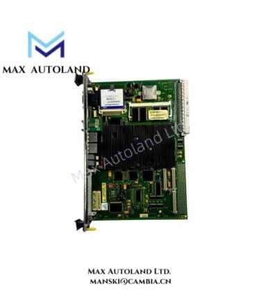
Overview
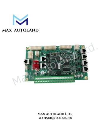
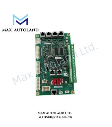
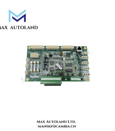
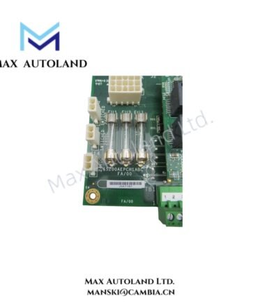
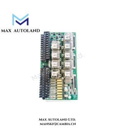
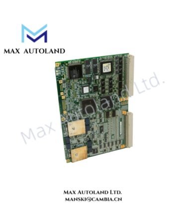
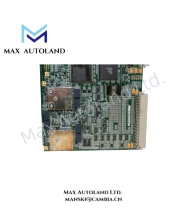
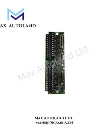
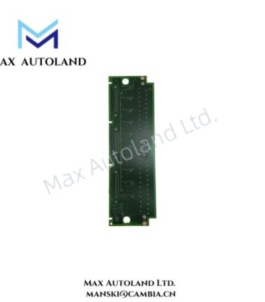
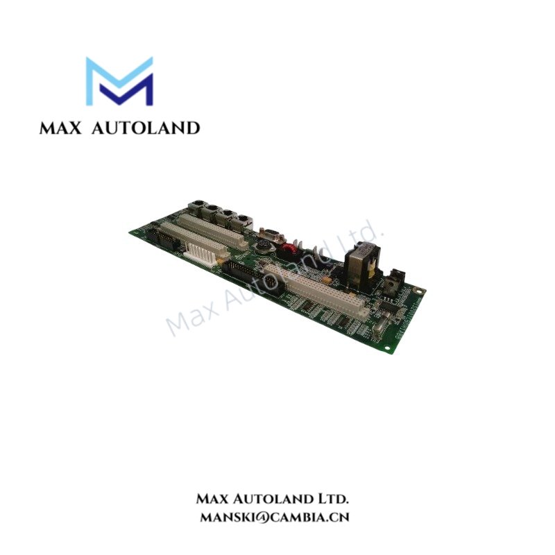
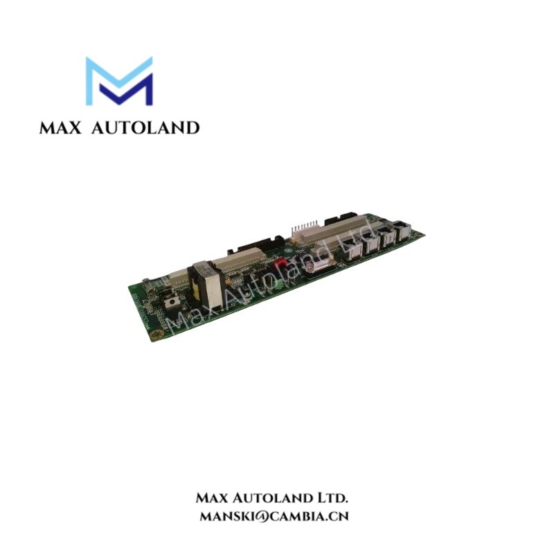
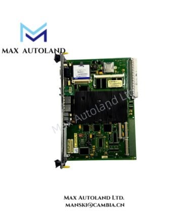
The GE IS200WORBH1A, also identified by the base model IS200WORBH1A, is described as a terminal board for field wiring interfaces within GE Speedtronic control systems. Its specific signal types, I/O assignments, and compatibility with Mark VI or Mark VIe hardware require confirmation against the applicable GE documentation.
Hardware Specifications
| Parameter | Specification |
|---|---|
| Model | IS200WORBH1A |
| Brand | General Electric (GE) |
| Series | Speedtronic Mark VI / Mark VIe |
| Product Type | Terminal Board |
| Primary Function | Field wiring interface |
| Mounting | Panel mounting is described; exact mounting requirements require verification |
| Configuration Software | ToolboxST is associated with GE Mark VIe systems; model-specific support requires verification |
Field Wiring and I/O Interface Considerations
A terminal board provides physical connection points for conductors and associated control-system interfaces. However, the supplied information does not establish the IS200WORBH1A’s supported signal types, terminal assignments, channel count, or I/O pack connections.
Before integrating this board into a Mark VI or Mark VIe installation, verify its hardware revision, connector layout, wiring diagram, and system compatibility. Do not assign field signals based solely on the general terminal-board description.
Frequently Asked Questions
Q: Can the IS200WORBH1A be installed in either Mark VI or Mark VIe systems?
A: Compatibility with both platforms has not been established by the supplied data. Confirm the exact board number and revision against the system hardware documentation before installation.
Q: What are the operating temperature and power consumption specifications?
A: The supplied information does not provide verified values. Consult the applicable GE technical documentation rather than applying general Mark VIe environmental ratings to this board.
Q: Does the IS200WORBH1A support hot swapping?
A: Hot-swap capability has not been verified. Isolate the relevant equipment and follow the manufacturer’s approved replacement procedure unless the documentation explicitly permits energized removal or installation.
Field Installation Guidelines
- Verify the complete part number and revision against the equipment bill of materials.
- Confirm the mounting arrangement, connector orientation, and terminal assignments using the applicable wiring documentation.
- Isolate power and follow site lockout/tagout procedures before handling the board or field wiring.
- Route signal wiring separately from high-current and switching conductors where practical to reduce electrical interference.
- Apply cable shielding and grounding according to the system wiring design. Avoid introducing unintended ground paths.
- Inspect connectors and terminals for damage, contamination, or loose connections before installation.
- After installation, verify wiring continuity and signal assignments before returning the control system to service.